Single-pipe cylinder-type reformer

a technology of cylinder type and reformer, which is applied in the direction of sustainable manufacturing/processing, physical/chemical process catalysts, lighting and heating apparatus, etc., can solve the problems of high efficiency, low efficiency, and start-up performance, and achieve good start-up performance and reduce size and weight

Inactive Publication Date: 2006-05-02
TOKYO GAS CO LTD
View PDF21 Cites 18 Cited by
  • Summary
  • Abstract
  • Description
  • Claims
  • Application Information

AI Technical Summary

Benefits of technology

[0011]The present invention has been made in consideration of the above problems in the prior art, has as an object to provide a single-pipe cylinder-type reformer which can generate a reformed gas with a low CO concentration, has an efficient, good start-up performance, realizes reduction in size and weight and does not emit excessive heat.

Problems solved by technology

However, providing a CO modifier and a CO selective oxidizer for this purpose independently of the single-pipe cylinder-type reformer is not preferable in terms of downsizing, high efficiency, and start-up performance.
WO00 / 63114, too much heat is radiated to the outside, and heat is not appropriately supplied to and discharged from the respective portions.

Method used


Image

  • Single-pipe cylinder-type reformer
  • Single-pipe cylinder-type reformer
  • Single-pipe cylinder-type reformer

Examples


Embodiment Construction

[0056]A single-pipe cylinder-type reformer according to a preferred embodiment of the present invention will be described with reference to the accompanying drawings.

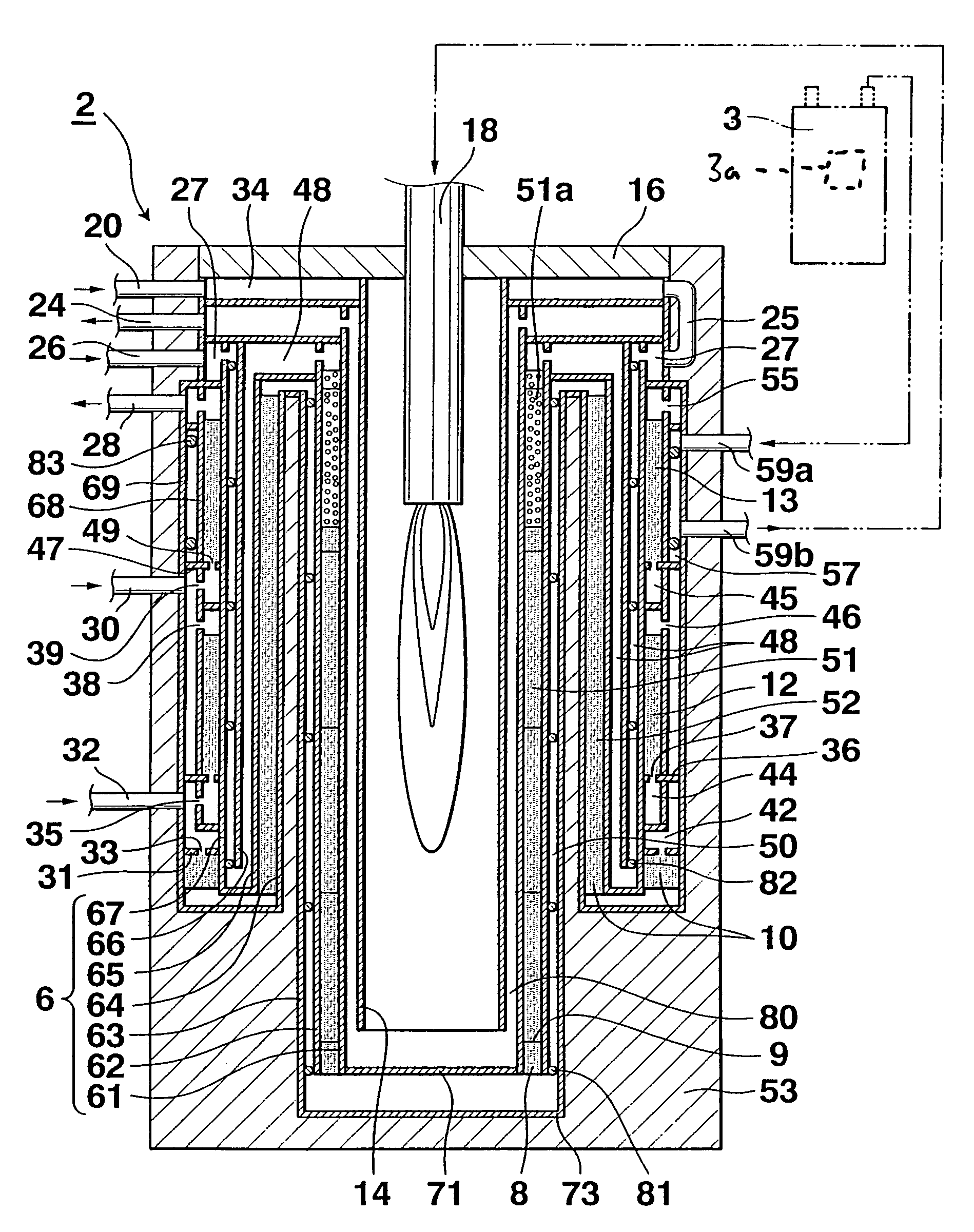
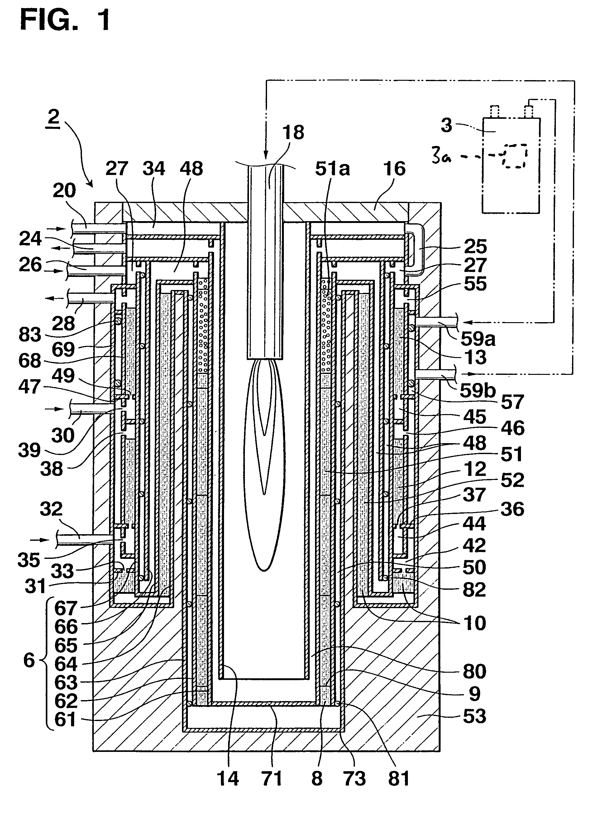
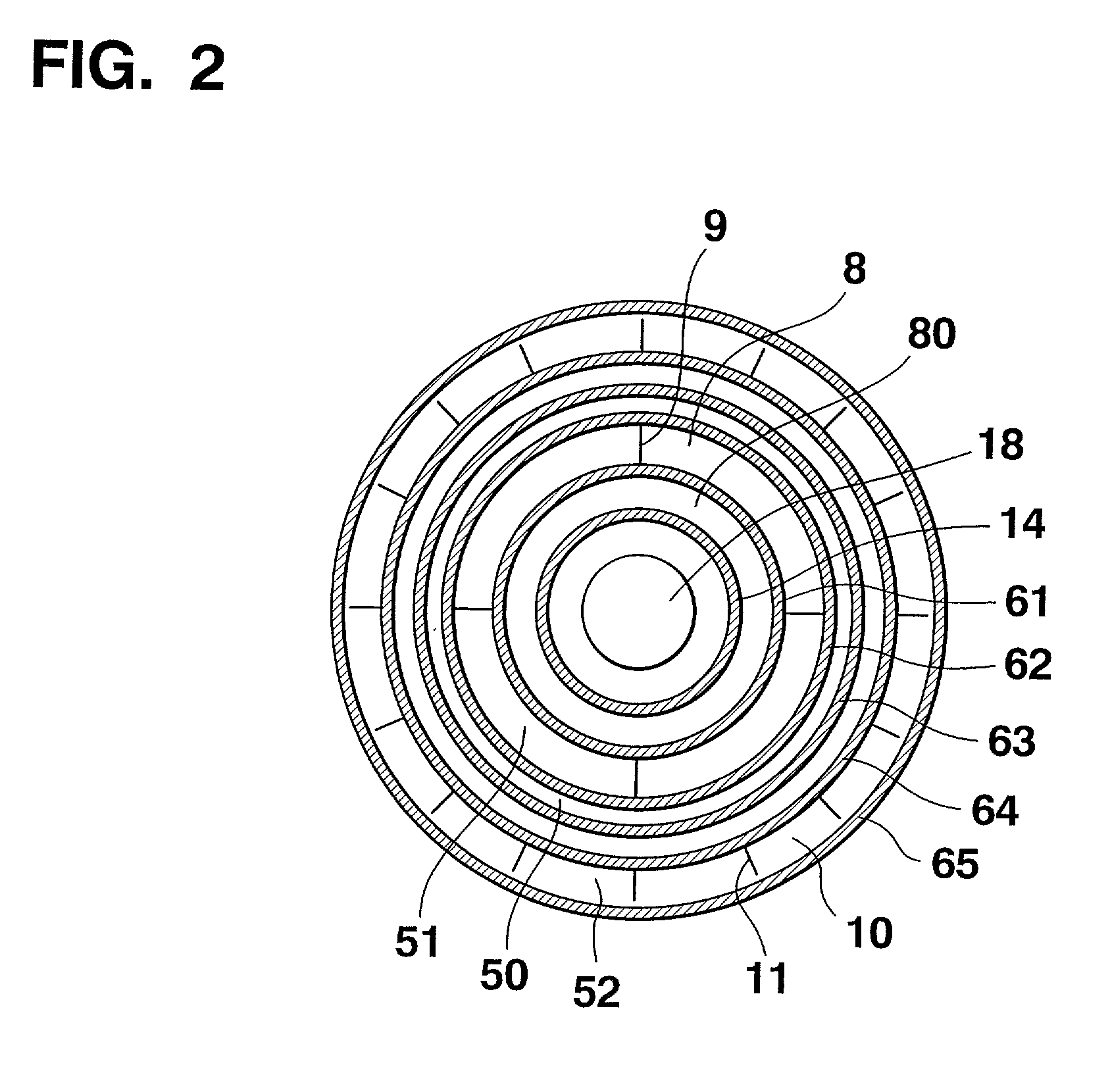
[0057]FIG. 1 shows the schematic arrangement of a single-pipe cylinder-type reformer. In the following description, a single-pipe cylinder-type reformer, the respective cylinders of which stand vertically and the burner of which is attached to one end (an upper portion in FIG. 1) of the reformer, as shown in FIG. 1, will be described as an example.

[0058]A reformer 2 is constituted by a plurality of circular cylinders 6 comprised of first to ninth cylinders 61 to 69 mounted coaxially, ring-shaped gaps defined between the respective cylinders, which forms a zigzag gas flow path having a plurality of gas flow path sections disposed between every pair of adjacent circular cylinders, a burner 18 mounted on the side of one end of the first cylinder 61 and at the center thereof, a reforming catalyst layer 8, CO modifying catal...


PUM

PropertyMeasurementUnit
axial lengthsaaaaaaaaaa
concentrationaaaaaaaaaa
volumeaaaaaaaaaa

Abstract

A single-pipe cylinder-type reformer includes a plurality of circular cylinders standing upright coaxially and forming therebetween a zigzag gas flow path allowing a raw material gas to flow therein, a radiation cylinder coaxially arranged inside the plurality of circular cylinders, a burner arranged at one end of a center of the radiation cylinder for generating a combustion gas, a reforming catalyst layer obtained by packing with a reforming catalyst at least a first gas flow path section of the gas flow path closest to the burner. A metal pre-heat layer formed on an upstream side of the reforming catalyst layer is packed with a metal packing. Helical dividing means are provided in each gas flow path section of the gas flow path to extend in the axial direction of the circular cylinders. The helical dividing means helically divide a gas and make it flow through the first gas flow section.

Description

BACKGROUND OF THE INVENTION[0001]1. Field of the Invention[0002]The present invention relates to a single-pipe cylinder-type reformer for manufacturing a hydrogen-rich reformed gas by steam-reforming a hydrocarbon-based fuel such as a city gas or LPG and, more particularly, to a reformer used in a solid-state polymer-type fuel cell.[0003]2. Description of the Prior Art[0004]A reformer is an apparatus for generating a reformed gas with a high hydrogen concentration by steam-reforming a raw material gas such as a city gas or LPG, and is widely used when manufacturing hydrogen used in an optical fiber or semiconductor manufacturing process, a fuel cell and the like.[0005]The steam-reforming reaction performed by a reformer is an endothermic reaction, and accordingly heating is needed to sustain the reaction. Usually, a combustor such as a burner is added to the reformer, and excessive hydrogen or reformed raw material gas from a fuel cell is heated by combusting it with the burner. As ...

Claims


Application Information

Patent Timeline
Patent Type & Authority Patents(United States)
IPC IPC(8): B01J8/06B01J8/04C01B3/38C01B3/48C01B3/58H01M8/06
CPCH01M8/0631B01J8/0465C01B3/384C01B3/48C01B3/583C01B2203/066C01B2203/047C01B2203/0811C01B2203/0816C01B2203/0822C01B2203/0827C01B2203/0838C01B2203/0844C01B2203/0866C01B2203/0883C01B2203/0894C01B2203/1011C01B2203/1241C01B2203/1276C01B2203/1294C01B2203/146C01B2203/1604C01B2203/82Y02E60/50B01J2208/00504B01J2208/00522B01J2208/00716B01J2208/0084B01J2208/025C01B2203/0233C01B2203/0283C01B2203/044C01B2203/0805Y02P20/10
Inventor KOMIYA, JUNMIURA, TOSHIYASU
Owner TOKYO GAS CO LTD
Why Eureka
Try Eureka