Apparatus and method for removing magnetic resonance imaging-induced noise from ECG signals

a technology of magnetic resonance imaging and noise removal, applied in the field of apparatus and method for removing magnetic resonance imaginginduced noise from ecg signals, can solve the problems of patient's illness, the environment of mri equipment itself is a very difficult one for the measurement of these small signals, and the patient's vital signs need to be monitored, so as to improve the performance of the equipmen

Active Publication Date: 2006-05-02
BAYER HEALTHCARE LLC
View PDF32 Cites 57 Cited by
  • Summary
  • Abstract
  • Description
  • Claims
  • Application Information

AI Technical Summary

Benefits of technology

[0012]In another aspect, the present invention provides an apparatus and method for adapting or improving a conventional or existing ECG monitor. The MRI noise reduction circuitry present in the conventional or existing ECG m...

Problems solved by technology

Or, the patient may be so ill that his or her vital signs need to be monitored during the imaging procedure.
However, the MRI equipment itself provides a very difficult environment for the measurement of these small signals.
This noise or interference makes it difficult for the health care professional or the MRI imaging system to readily observe or monitor the patient's ECG.
Several approaches are de...

Method used


Image

  • Apparatus and method for removing magnetic resonance imaging-induced noise from ECG signals
  • Apparatus and method for removing magnetic resonance imaging-induced noise from ECG signals
  • Apparatus and method for removing magnetic resonance imaging-induced noise from ECG signals

Examples


Embodiment Construction

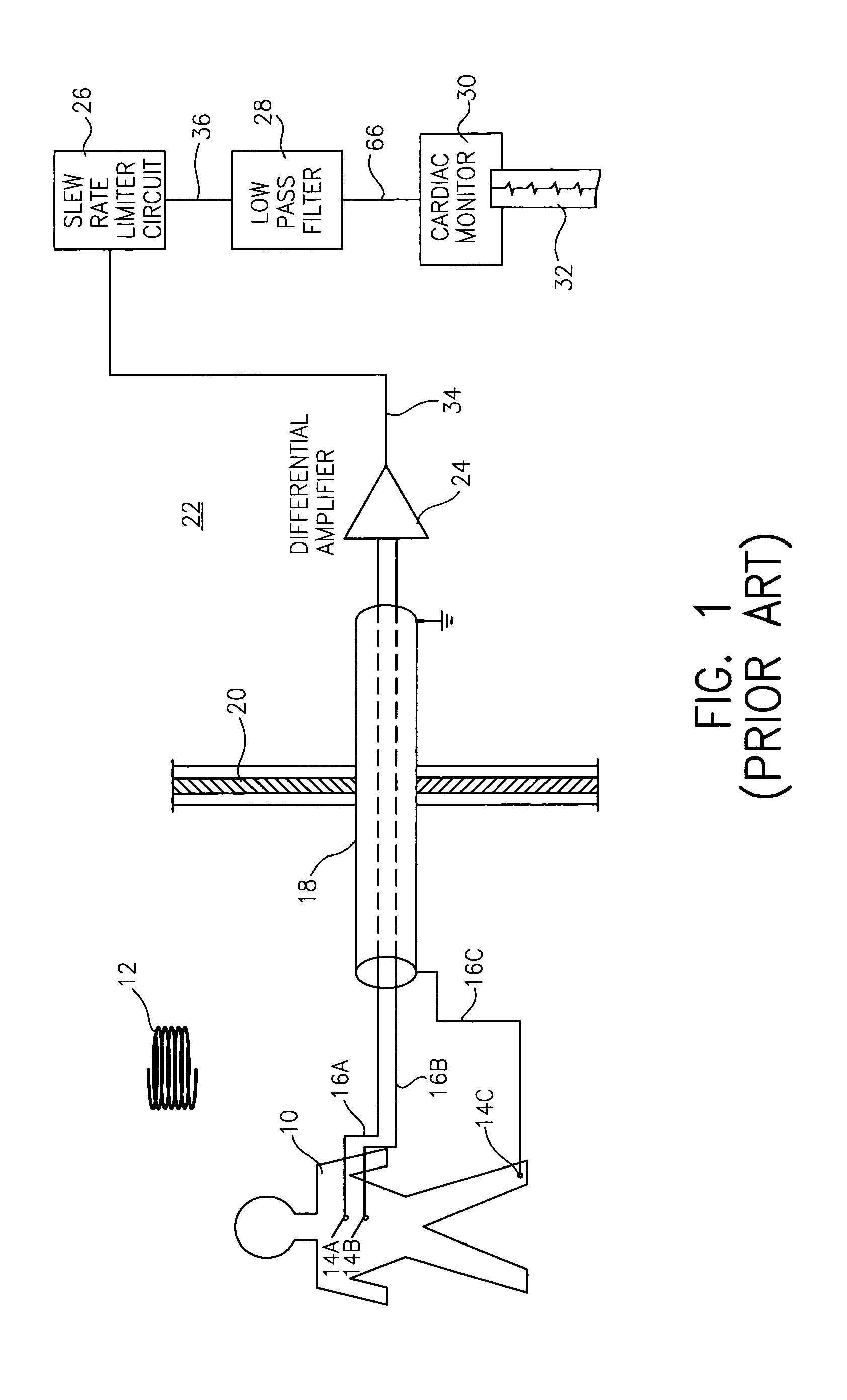
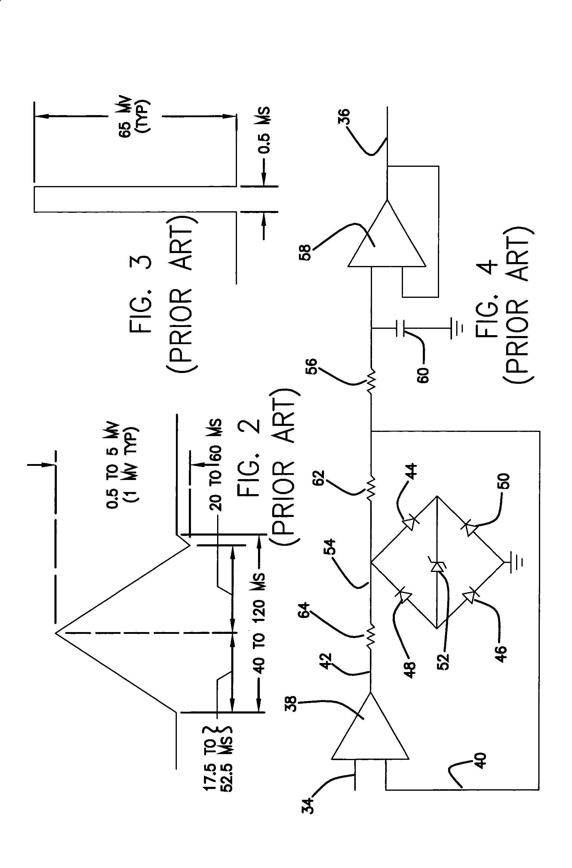
[0021]In a preferred and non-limiting embodiment, the present invention provides an improvement and expansion on U.S. Pat. No. 4,991,580 by John C. Moore, the contents of which are included herein by reference. FIGS. 1 though 4 from the Moore patent are reproduced as FIGS. 1 through 4 appended hereto.

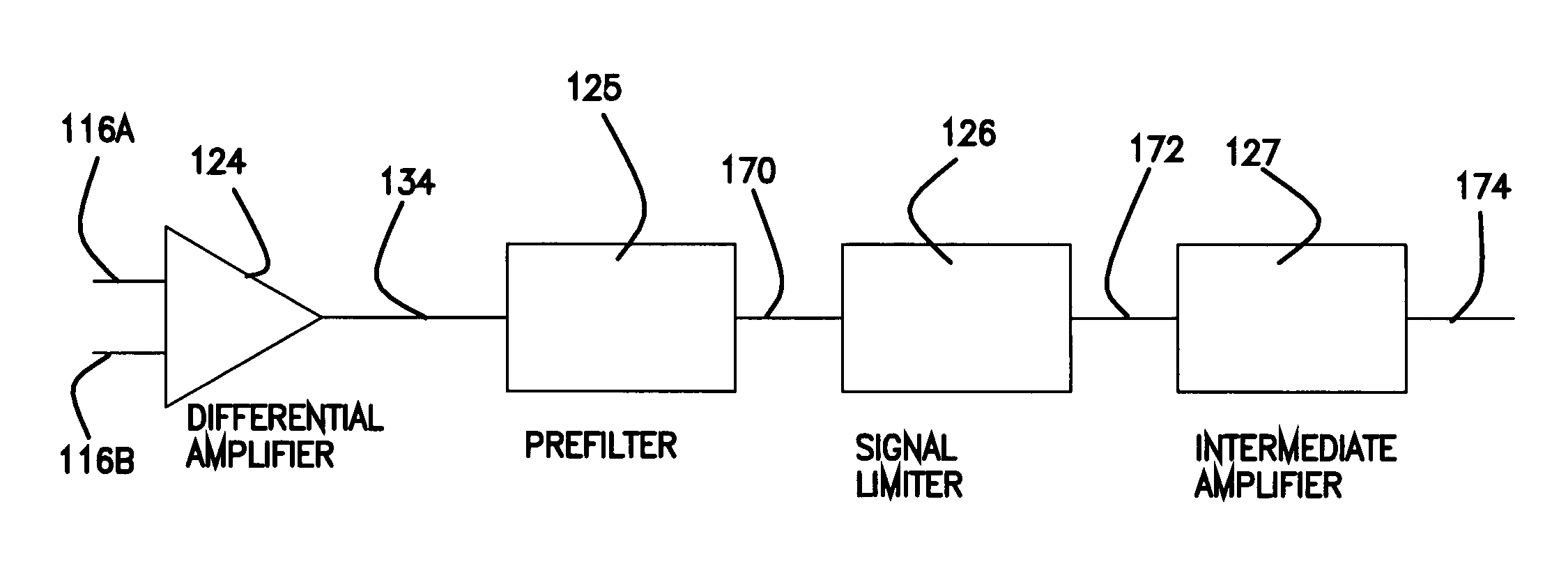
[0022]FIG. 5 is a block diagram of the preferred embodiment of the present invention. 116A and 116B represent the ECG signal inputs that are corrupted with induced MRI interference or noise from a MRI imaging procedure. The differential amplifier 124 provides an output 134 that is a function of the difference between the two inputs while rejecting common mode signals. The gain is approximately 7. The prefilter 125 is preferably a single pole low pass filter with a cutoff frequency below that of the gradient induced noise in the thousands of Hertz range and well above the ECG signal frequencies of interest, which are in the tens of Hertz range. Preferable the filter has a cutoff of 80 Hz...


PUM


Abstract

An apparatus and method is provided for improving the quality of electrocardiogram (ECG) signals obtained from a patient undergoing magnetic resonance imaging (MRI) wherein the ECG signal has relatively high levels of noise or interference voltages induced on it by changing magnetic fields. The apparatus includes the arrangement of a differential amplifier, a prefilter, a signal limiter (SL) circuit and an intermediate amplifier with an integral low pas filter. The prefilter limits the rise time or high frequency component of the noise or interfering voltages induced on the ECG that are presented to the signal limiter.

Description

CROSS REFERENCE TO RELATED APPLICATION[0001]This application claims the benefit of U.S. Provisional Application Ser. No. 60 / 328,076, filed on Oct. 9, 2001, the contents of which are incorporated herein by reference.BACKGROUND OF THE INVENTION[0002]Magnetic Resonance Imaging (MRI) provides medical diagnostic information that can be difficult or impossible to obtain otherwise. This information often requires that the electrocardiogram (ECG) of the patient be monitored or measured during imaging. One reason for monitoring ECG signals is to synchronize the acquisition of images with the heart beat to, for example, reduce motion artifacts associated with the heart beat in the acquired images and to obtain dynamic images of the heart. Or, the patient may be so ill that his or her vital signs need to be monitored during the imaging procedure. Further, the effect of pharmacological stressors can be monitored via ECG signals. And, as medical science improves, other uses will be developed as ...

Claims


Application Information

Patent Timeline
IPC IPC(8): A61B5/0402A61B5/00
CPCA61B5/0428Y10S128/901A61B5/055A61B5/30
Inventor BROSOVICH, JOHN A.YANNIELLO, MICHAEL J.YARZEBINSKI, ALBERT J.
Owner BAYER HEALTHCARE LLC
Why Eureka
Try Eureka