
Method for programming operator system interface with a simulator

Inactive Publication Date: 2006-05-02
LOCKHEED MARTIN CORP
View PDF37 Cites 13 Cited by
  • Summary
  • Abstract
  • Description
  • Claims
  • Application Information

AI Technical Summary

Benefits of technology

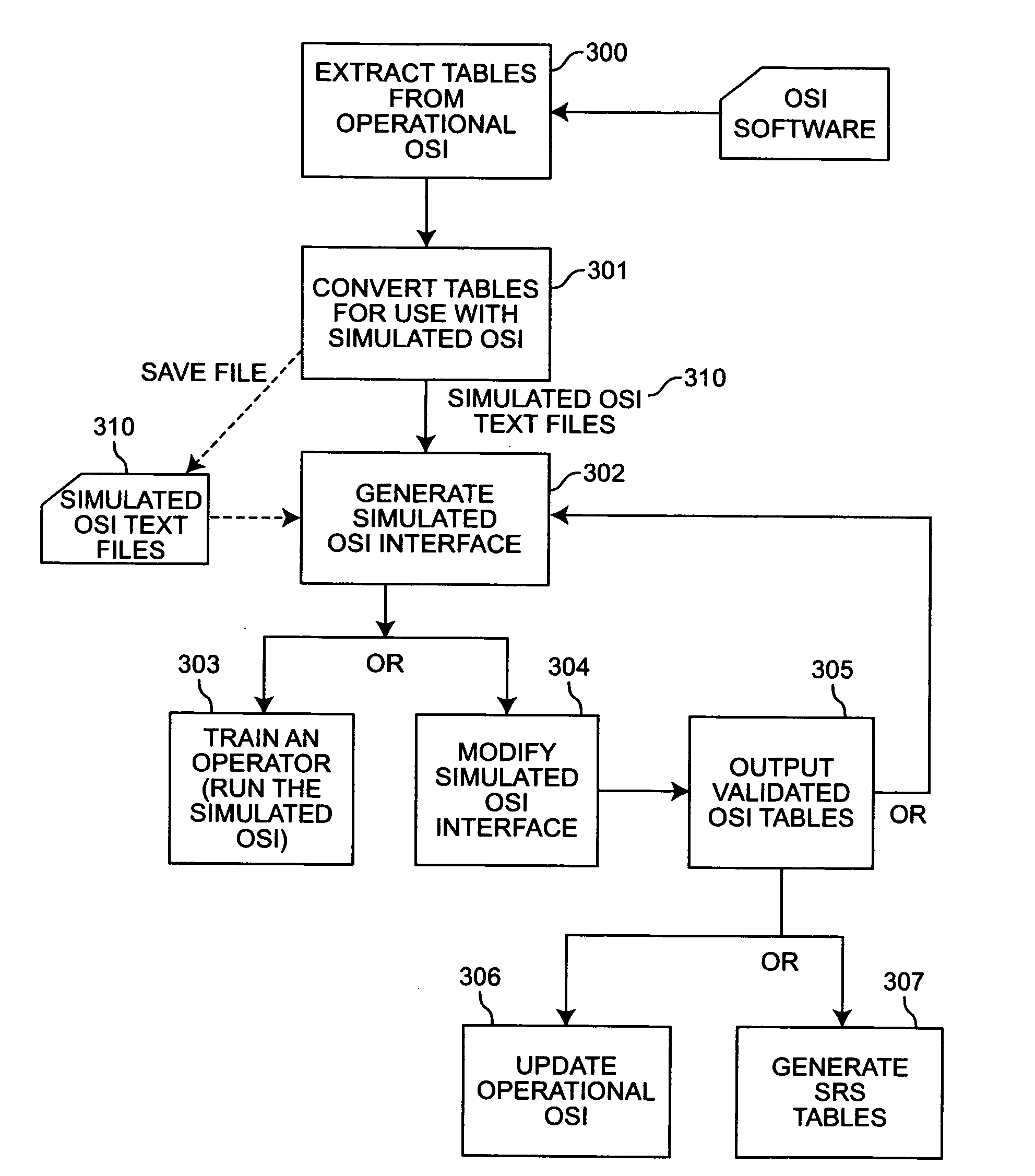
[0011]According to the invention, source code of an operational OSI is plugged directly into a conversion program, or “wrapper”, that takes the operational source code and converts it into input files for the OSI Trainer files and converts them into operational source code. Code developed using the “wrapper” plugs directly into the operational software; therefore, dual configuration management requirements of an independent program are avoided. This advantage of the present invention which uses the actual Control and Display (C&D) code eliminates the expected discrepancies between the operational software and the simulation over the life of a program.
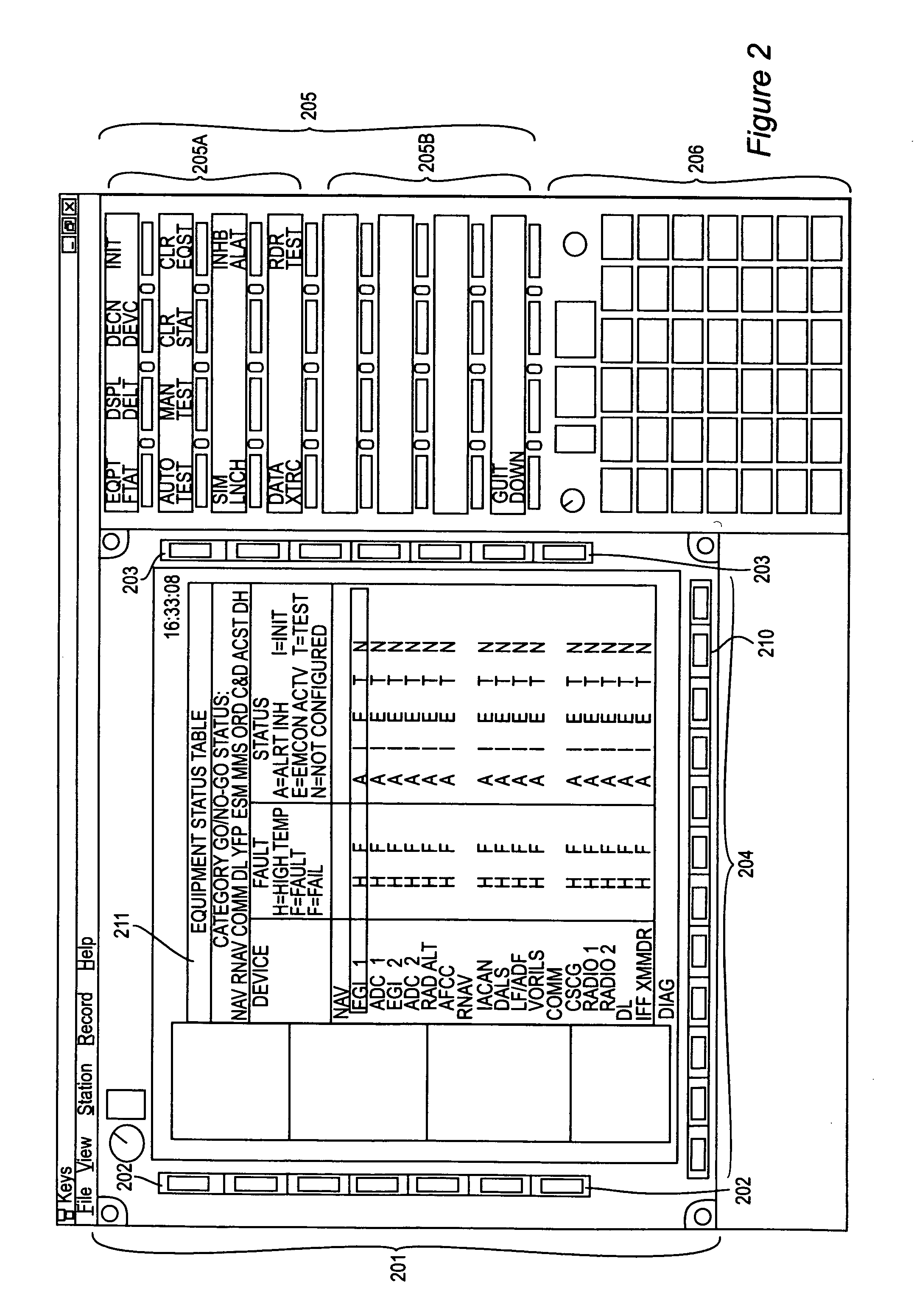
[0012]In the preferred embodiment, a simulation environment in a desk top computing environment is used to develop the operator system interface. Existing Avionics Operation Program (AOP) Ada language software tables are read into the simulator to define the keysets that the operator sees during the simulation / training. The tables can be modified in the simulator to output new tables in order to prototype a new operator system interface. Consequently, the software developer can use the simulator to create code tables rather than having to write new code. Also, the simulator is coded using parts of the AOP data structure and converts it for simulation. Simulation code can then be reconverted to AOP tables for configuring new key assignments and MFD menus in the operational system.
[0013]The process starts by taking existing code, for example the Multi-Mission Helicopter (MMH) AOP Ada language software data structures, and converting it into input files for the simulator which would then replicate the actual system software behavior. An operator could use this customized simulator for training for the MMH C&D. The input files could be easily modified by a developer to reflect proposed key moding and menu changes, run under the simulation to verify design, then converted directly into the same computer language code which was drawn from the system software. Thus enabling the operational system to be reprogrammed directly from the tables generated by the simulation prototype. The tables can then be output in an easy to read format that can be easily imported into a Software Requirement Specification, if necessary, for the targeted application.
[0014]This provides an efficient, convenient method of moving specific key legends / functions to other matrix or tree locations and allows new logic that controls key availability / activation (and eventually Window / Menu behavior) based on Operator Keyset and Window / Menu selections. The intent here is to allow interim growth in functionality prior to adopting a complete mission module by using a socket type architecture that allows implementation / modification of specific key functionality.

Problems solved by technology

In the past, a great deal of computer code had to be written to create and maintain these functions, and changes were expensive as the design moved through the development process.
Currently, the lack of specific written guidance on window moding and behavior exposes the likelihood that an imperfect interpretation of a C&D system will be made (i.e., actual requirements not detected early in development).
This is inherently counter-productive to the end objective.
This lack of an easy ability to prototype the OSI often results in the final coded system that does not fully correspond to, or map to, the users' requirements.
The Controls and Display (C&D) interface is complex with intricately interwoven moding, behaviors and functionality.

Method used


Image

  • Method for programming operator system interface with a simulator
  • Method for programming operator system interface with a simulator
  • Method for programming operator system interface with a simulator

Examples


Embodiment Construction

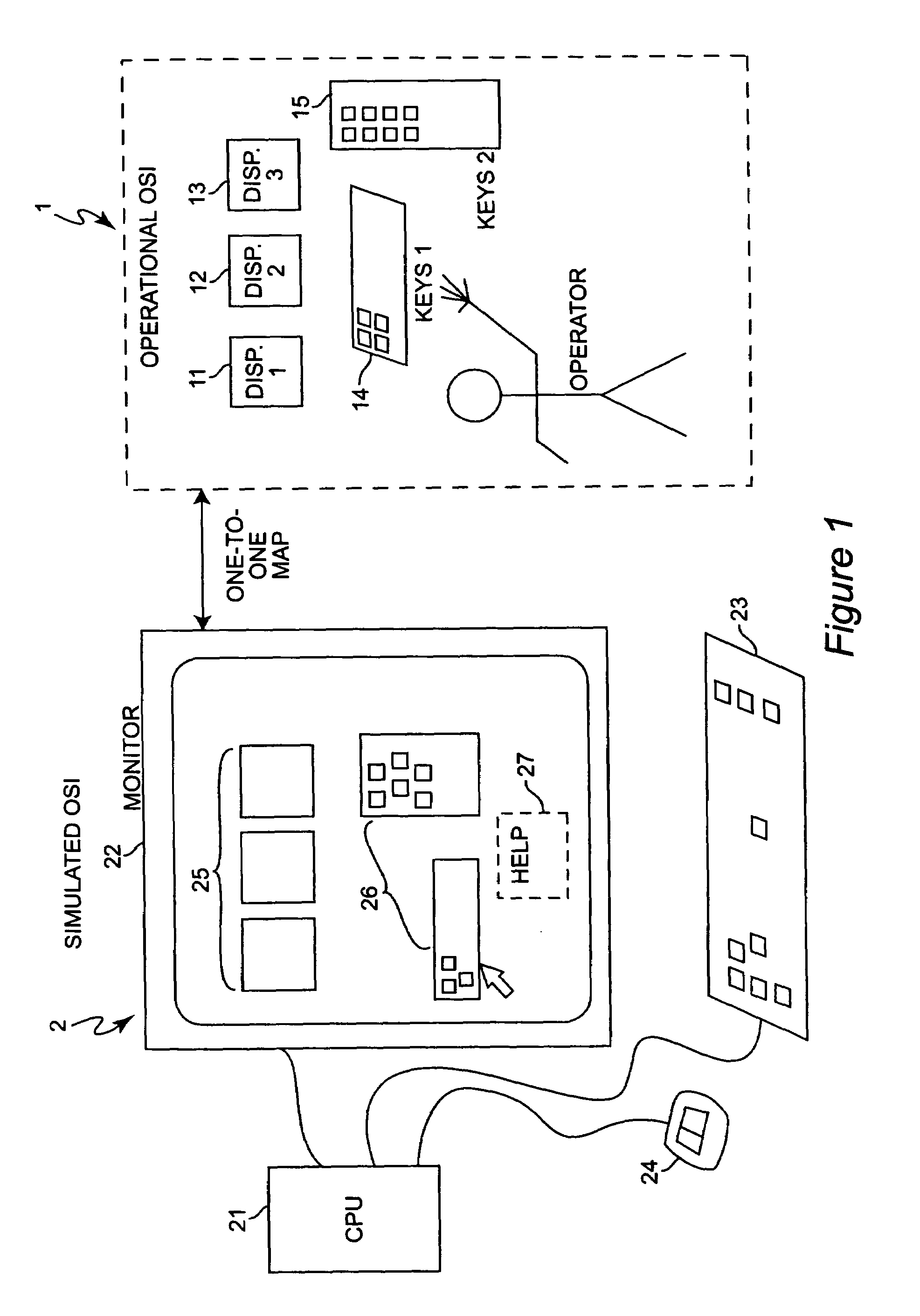
[0023]Referring now to the drawings, and more particularly to FIG. 1, there is shown a one-to-one mapping of the operational Operator System Interface (OSI) 1 to the simulated OSI 2. The actual operational system comprises a set of displays 11, 12 and 13 and a number of keypads 14 and 15. The simulated OSI 2 comprises a Central Processing Unit (CPU) 21 running the simulation software, a display device or monitor 22, a keyboard or other input device 23 and a mouse or other pointing device 24. The control and display components of the operational OSI are represented in the simulated OSI 2 on the monitor 22. The displays 11, 12 and 13 are represented as a simulated set of displays 25. The keysets 14 and 15, are represented as a simulated set of keys 26. A help window 27 is also displayed to facilitate operator training.

[0024]In the preferred embodiment of the present invention, re-utilization of Avionics Operation Program (AOP) code is maximized to facilitate an efficient Control and D...


PUM


Abstract

A process that takes converted system software code as input to a program created with a commercial compiler to produce a simulated Operator System Interface. An Operator System Interface is produced using program data structures rather than extensive emulation or updating of program source code. These files can then be modified or updated and converted back to both drive the system software and the Software Specification. This eliminates extensive manpower intensive emulation, and significantly reduces update work on actual system source code.

Description

BACKGROUND OF THE INVENTION[0001]1. Field of the Invention[0002]The present invention generally relates to user interfaces to simulation software and, more particularly, to a process that takes converted system software code as input to a program created with a commercial compiler to produce a simulated Operator System Interface.[0003]2. Background Description[0004]In modern, highly integrated aircraft there normally is found a complicated Operator System Interface (OSI) utilizing both a programmable keyset and multi function display (MFD). For example, the Multi-Mission Helicopter (MMH) employs I / 0 (input / output) devices such as programmable keysets and Multi Function Displays. In the MMH it is necessary to program both keyset layering and requisite menus for system and menu control. Specific keys access menus, other key layers or functions. Other aircraft system solutions could use a combination of an application specific softkey hierarchy and Central Display Unit (CDU) for data e...

Claims


Application Information

Patent Timeline
IPC IPC(8): G06F17/50G05B11/01G06F9/00G09B19/16G09B9/08
CPCG06F8/38G06F3/0238
Inventor MUNGER, ROBERT J.JENNINGS, NATHANIEL H.
Owner LOCKHEED MARTIN CORP
Learn More