Method of simultaneously and directly generating an angular position and angular velocity measurement in a micromachined gyroscope

a micro-machined gyroscope and simultaneous generation technology, applied in the field of mems gyroscopes, can solve the problems of reducing performance, reducing performance, and prior art control electronics of gyroscopes that do not allow simultaneous detection of angular position and angular velocity, and achieves large quality, small size, and high performance in attitude measurement.

Active Publication Date: 2006-05-09
RGT UNIV OF CALIFORNIA
View PDF5 Cites 8 Cited by
  • Summary
  • Abstract
  • Description
  • Claims
  • Application Information

AI Technical Summary

Benefits of technology

[0008]The gyroscope of the invention measures angle directly, avoiding the integration of electronic errors and allowing for higher performance in attitude measurement. The capability to simultaneously measure angular rate allows flexibility for the end user who can use the device for rate and angle measurement without additional electronics. These performance improvements and flexibility in usage would allow for long term attitude sensing applications such as implantable prosthetics, micro-vehicle navigation, structural health monitoring, and long range smart munitions. Through the fabrication of the device using lithographic methods, the device can be made small and in large qualities, resulting in low costs and low power consumption.

Problems solved by technology

However, these devices require integration of the electronic output signal to obtain orientation, magnifying drift and noise errors causing reduced performance.
However, the prior art control electronics of the gyroscope does not allow for the simultaneous detection of angular position and angular velocity.
These devices require integration of the electronic output signal to obtain position, magnifying drift and noise errors which results in reduced performance.

Method used


Image

  • Method of simultaneously and directly generating an angular position and angular velocity measurement in a micromachined gyroscope
  • Method of simultaneously and directly generating an angular position and angular velocity measurement in a micromachined gyroscope
  • Method of simultaneously and directly generating an angular position and angular velocity measurement in a micromachined gyroscope

Examples


Embodiment Construction

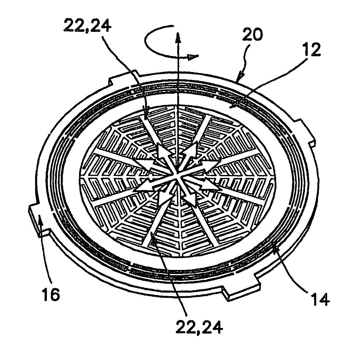
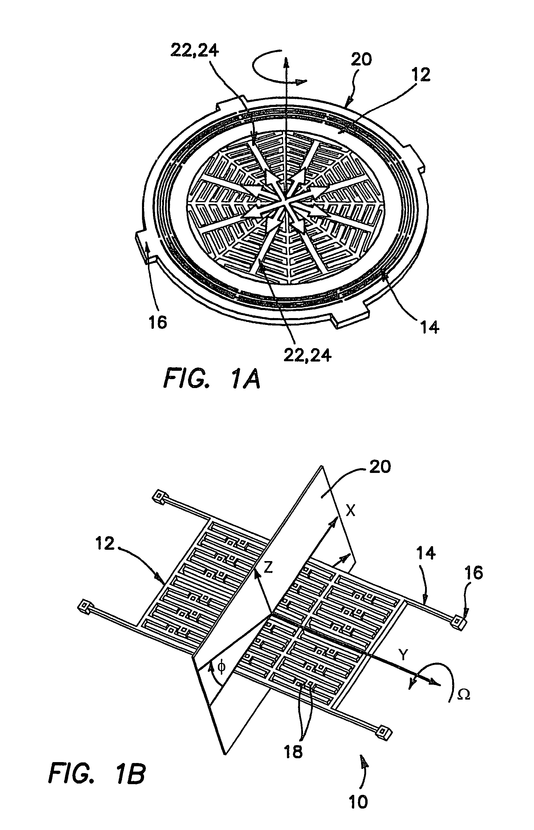
[0048]Possible realizations of x, y, and z gyroscopes 10 are shown in FIGS. 1a and 1b. The micromachined gyroscopes 10 each utilize a vibrational “lumped mass system “rigidly attached to the chip or substrate on which gyro 10 is ultimately mounted (not shown) via suspension members 14 which are attached to the proof mass 12 on one end and anchored to the chip substrate through anchors 16 on the other. The suspension members 14 are designed to allow compliance within the “working plane”20 while restricting motion along the axis of rotation. In addition, it is necessary for suspension members 14 to be isotropic within the “working plane”20 in order to allow the unperturbed precession of the oscillation pattern. Electrostatic forces are used for the actuation of the gyro 10. Actuation in this way is performed by application of DC and AC voltages on the fixed electrodes 18 of the gyros 10. Similarly, position and velocity are detected by output current induced by the motion of the gyro ...


PUM


Abstract

A sensor is fabricated with micron feature sizes capable of simultaneously measuring absolute angles of rotation and angular rotational rates. The measurements are made directly from the position and velocity of the device without the need for electronic integration or differentiation. The device measures angle directly, avoiding the integration of electronic errors and allowing for higher performance in attitude measurement. These performance improvements and flexibility in usage allow for long term attitude sensing applications such as implantable prosthetics, micro-vehicle navigation, structural health monitoring, and long range smart munitions. Through the fabrication of the device using lithographic methods, the device can be made small and in large qualities, resulting in low costs and low power consumption.

Description

RELATED APPLICATIONS[0001]The present application is related to U.S. Provisional Patent Application Ser. No. 60 / 527,419, filed on Dec. 4, 2003, which is incorporated herein by reference and to which priority is claimed pursuant to 35 USC 119.BACKGROUND OF THE INVENTION[0002]1. Field of the Invention[0003]The invention is in the field of MEMS gyroscopes capable of simultaneous measurement of angular position and angular rate.[0004]2. Description of the Prior Art[0005]All micromachined gyroscopes are vibratory in nature, measuring either angular rates by detecting energy coupled between orthogonal vibration modes due to Coriolis force or angle of rotation through the precession of an oscillation pattern. In a rate gyroscope, a structural element is forced into oscillation in one principle structural mode, designated the “drive” mode. The presence of rotation induced Coriolis force couples the sustained oscillation into an orthogonal structural mode, designated the “sense” mode. The ma...

Claims


Application Information

Patent Timeline
Patent Type & Authority Patents(United States)
IPC IPC(8): G01C19/00G01P3/44G01C19/56G01P1/04G01P9/04
CPCG01C19/5719
Inventor PAINTER, CHRISSHKEL, ANDREI M.
Owner RGT UNIV OF CALIFORNIA
Why Eureka
Try Eureka