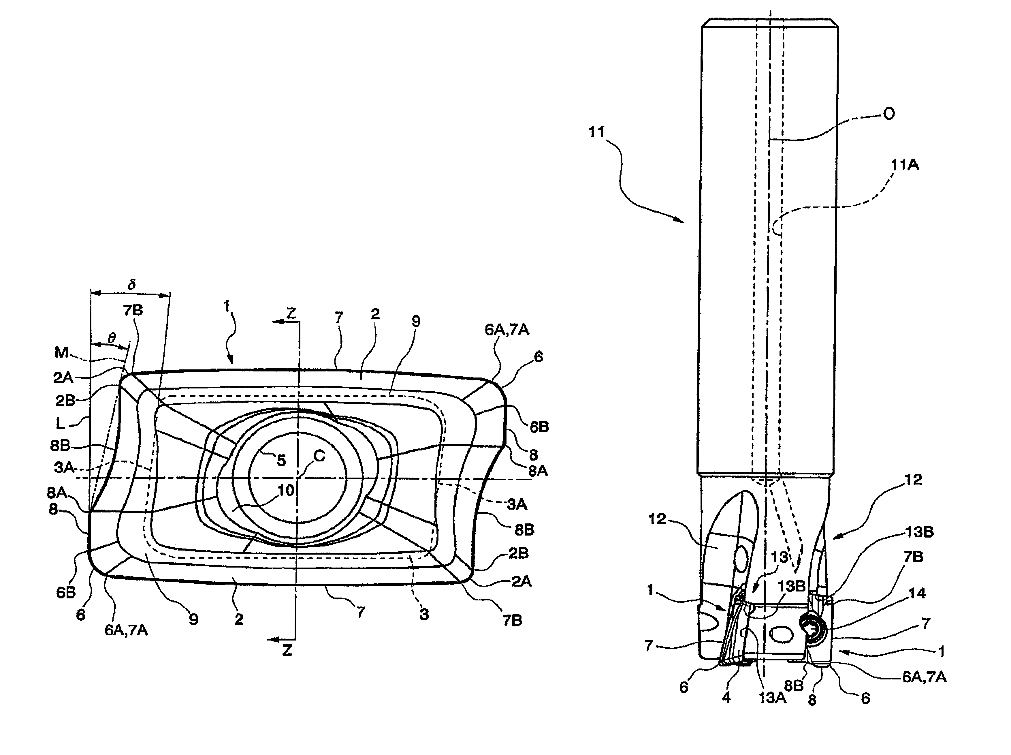
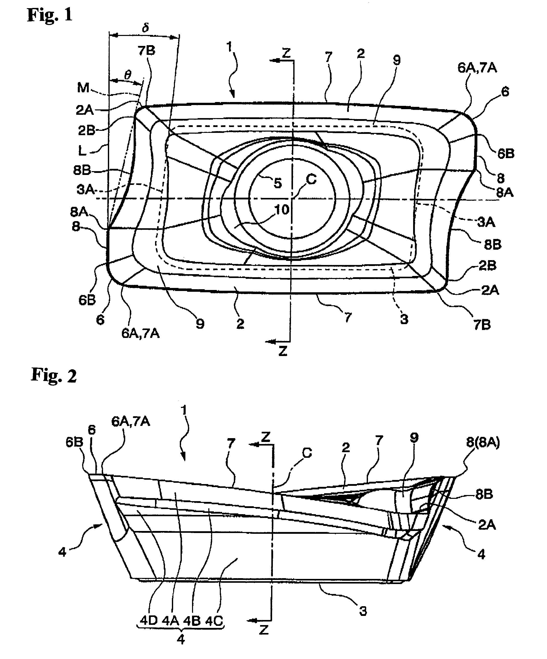
[0010]The present invention has been made under the above situations. Accordingly, it is an object of the present invention to provide a insert and a rotary cutting tool which can make a joint (seam line) between individual vertically machined surfaces inconspicuous even when a rotary cutting tool is moved step by step to form a deep and vertically
machined surface, which can obtain high precision and
high surface quality over the entire vertically
machined surface, and which can improve the
chip separation to allow higher speed cutting.
[0012]As described above, in the insert and rotary cutting tool in which a main cutting edge is not included on a cylindrical surface about a rotation axis of a tool body of the rotary cutting tool, but a
projection line (a
projection line projected onto a plane including an axis) of a rotation locus of the main cutting edge about the axis is formed in a shape of a convexly curved line, as seen from the top, which smoothly comes, at a middle portion of the main cutting edge, into contact with a cylindrical surface and which retreats inward from the cylindrical surface as it approaches both ends of the main cutting edge, even if the insert is mounted to a tool body with the main cutting edge inclined from a predetermined position, the projection line itself to be transferred to a vertically machined surface to be
cut does not vary as long as the inclination of the main cutting edge extends has a direction along a convex arc defined by the projection line. On the other hand, as described above, a joint between vertically machined surfaces when the rotary cutting tool is moved step by step to perform cutting, has a chevron-shaped section in which the arcuate projection line and another projection line obtained by shifting and transferring the convex arcuate projection line in the axial direction overlap each other. However, the
radius of an arc defined by the projection line is set to be large, so that the height of the chevron can be suppressed so as not to be conspicuous, and the respective machined surfaces can be a vertically machined surface more approximate to a flat face. Moreover, even if the cylindrical surfaces do not coincide with each other due to bending of the tool body when the rotary cutting tool is moved step by step in that manner, the joint therebetween does not become large. As a result, it is possible to obtain a vertically machined surface with high precision and height quality without any conspicuous joint.
[0013]Further, the main cutting edge is formed in a shape of a convexly curved line which extends toward the seat face while being convexly curved as it approaches the other end of the main cutting edge from the one end of the main cutting edge as seen from the side facing the rake face. Accordingly, the rake face connected to the main cutting edge is also formed in a shape of a convexly curved line which is convexly curved similarly to the main cutting edge. In addition to the above, the main cutting edge is formed in a shape of a convexly curved line as also seen from the top such that the projection line of the main cutting edge forms a convexly
arcuate shape. Thus, when a vertically machined surface is
cut by the main cutting edge, a
chip which is largely curved in a recessed shape and to which the projection line is transferred flows out onto the convexly curved rake face. Accordingly, it is possible to more easily separate chips from the rake face and dispose them rapidly. It is also possible to further promote high-speed cutting and thus to remarkably improve the cutting efficiency. Moreover, the main cutting edge which extends toward the seat face while being convexly curved as it approaches the other end of the main cutting edge from the one end of the main cutting edge in this manner is mounted to extend rearward in the rotating direction as it approaches the rear end of the tool body. Therefore, it is possible to increase the axial
rake angle at the other end of the main cutting edge, i.e., at the rear end of the tool which is used at the time of deep cutting. Even when a wide
chip is produced at the time of such deep cutting, it is possible to maintain an excellent chip separation property.
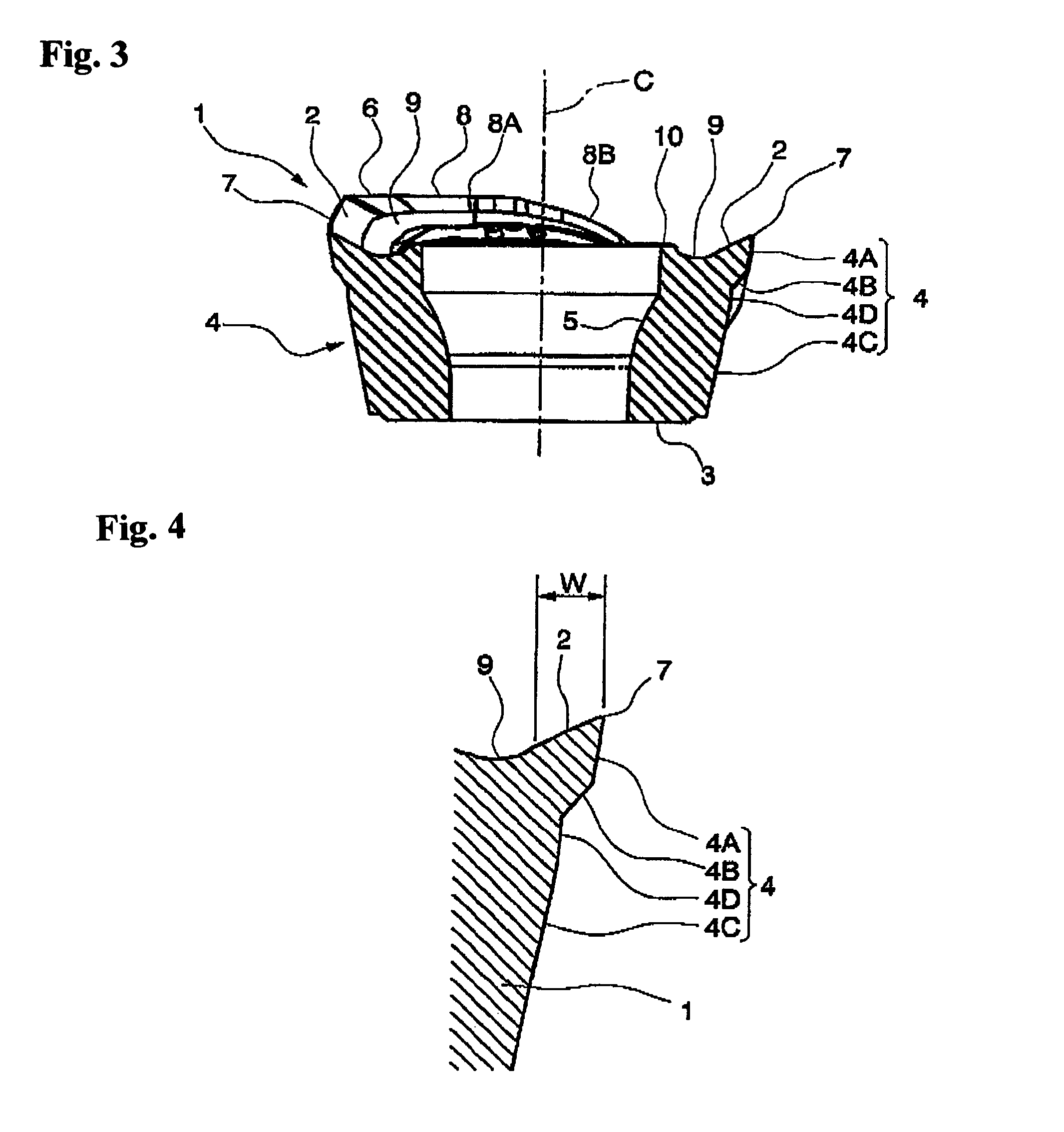
[0014]Moreover, in the insert of the present invention, the rake face connected to the main cutting edge can be formed to have an inclined face which is inclined inward from the rake face as it approaches the seat face, and the
rake angle of the rake face which is formed with respect to the main cutting edge with such a insert mounted to the tool body of the rotary cutting tool is set to be a positive angle. In this case, the inclination angle of the rake face which has the inclined face and is formed with respect to the seat face of the insert body gradually decreases from the one end of the main cutting edge toward the other end thereof, and the
rake angle defined by the rake face with the insert mounted to the tool body gradually decreases from the one end of the main cutting edge toward the other end thereof and then gradually increases. Thus, as described above, it is possible to prevent the main cutting edge which is inclined rearward in the rotating direction as it approaches the rear end of the tool body from being remarkably different at one end thereof at the distal end of the tool and at the other end thereof at the rear end of the tool. Also, the rake face can be convexly curved along the main cutting edge inside the rake face as described above such that a portion between both ends of the main cutting edge protrudes further than both ends of the main cutting edge. Thus, it is possible to further improve a chip separation property.
[0016]Also, when the relief face connected to the main cutting edge is formed with the first and second relief faces in that manner, at least the one end of the main cutting edge is formed with a planar third relief face which is connected to a portion of the second relief face at the seat face and extends perpendicularly to the seat face. Thereby, for example, as compared to a case in which a rake face is simply formed to gradually retreat from the first relief face toward the seat face as it approaches the seat face, it is possible to secure a larger thickness by virtue of side faces of the insert body at a portion of the second relief face immediately adjacent to the seat face. Accordingly, it is possible to secure particularly high cutting
edge strength at one end of the main cutting edge which is positioned forward in the rotating direction of the with the insert mounted to the insert main body and which bites into a workpiece for the first time. It is also possible to prevent the one end of the main cutting edge and the corner cutting edge connected thereto from being lost due to an
impact at the time of such
biting. On the other hand, the rotary cutting tool having such a insert mounted thereon often performs a
rubbing process in which a groove or recess having an inclined bottom face is formed in a workpiece by feeding the tool body toward the distal end obliquely with respect to the axis. When the rotary cutting tool is used for such a
rubbing process, as for the above-mentioned insert, a side
ridge of the rake face connected to the other end of the corner cutting edge, which is disposed at the distal end of the tool body, is formed with a sub-cutting edge extending from the other end of the corner cutting edge toward the inner periphery of the tool body with the insert mounted to the tool body, and a concave portion which is connected to the sub-cutting edge, reaches the other corner of the rake face opposite to the corner having the corner cutting edge formed therein, and is recessed to the inside of the rake face with respect to the extension line of the sub-cutting edge as seen from the top. Moreover, as for such a insert, as seen from the top, an angle of a tangential line touching both ends of the concave portion formed with respect to the extension line of the corner cutting edge is larger in a range of 5° to 20° than an angle at which a side
ridge of the other polygonal surface located on the opposite side to the side
ridge having the sub-cutting edge and the concave portion formed therein is formed with respect to the extension line.

