Electric motors for washdown, food processing, and chemical applications

a technology of electric motors and washdown facilities, applied in the direction of dynamo-electric machines, magnetic circuits characterised by insulating materials, supports/enclosements/casings, etc., can solve the problems of corrosive chemicals becoming dissolved in wastewater, harsh conditions for electric motors utilized in manufacturing processes, and increasing humidity in the cleaning facility

Active Publication Date: 2006-05-09
BLUFFTON MOTOR WORKS
View PDF47 Cites 37 Cited by
  • Summary
  • Abstract
  • Description
  • Claims
  • Application Information

AI Technical Summary

Benefits of technology

[0008]The motor includes features for preventing moisture from entering into the motor casing and additional protection to those motor components which are prone to oxidative attack—in particular, the motor's stator assembly, which includes copper wire windings disposed around a laminated core, and the motor's bearings, which include components that provide protection for the internal components of the motor from moisture and chemicals.
[0010]The motor casing employed in the present invention is preferably manufactured from a corrosion-resistant material such as stainless steel. The open ends of the motor casing are flared (i.e., have a somewhat larger diameter when compared to the main body of the motor casing) to facilitate insertion of end bells into the motor casing and to prevent moisture build-up by facilitating drainage. The flared ends also create a place for the internal condensation to gather away from the windings and bearings. The flared ends of the motor casing may also contain drainage holes for removal of liquid away from the motor.
[0016]In order to counter this seepage, the motor of the present invention incorporates seals and washers in the region where the motor shaft passes, through the open end bell. The bearing assembly mounted in the open end bell has an outer face, which is protected by a one-way check seal, and a shaft lip seal disposed toward the motor exterior, and an inner face, which is disposed toward the motor interior. There is also a very small diametrical clearance between the shaft outer diameter and the end bell inner diameter to keep any foreign objects out. There are also four inter cavity drains which keep moisture from building up around the center hub and onto the seals regardless of mounting position. Finally, a stainless steel slinger is press fit onto the shaft to keep any high pressure spray or liquid material away from the check seal and the shaft lip seal.

Problems solved by technology

During the course of the cleaning operation, electric motors utilized in the manufacturing process are exposed to harsh, oxidative conditions.
In the course of the cleaning process, the level of humidity in the facility being cleaned increases and corrosive chemicals can become dissolved in the wastewater.
Nonetheless, the resultant high humidity, particularly in combination with dissolved chemicals in the atmosphere, produces a highly corrosive environment.
While precautions can be taken to lessen the ingress of moisture into the motor interior by employing multiple seals and water-tight fittings, some amount of corrosive solution will inevitably enter into the motor interior—around the shaft or through inlets for electrical wiring, resulting in chemical attack on the winding or bearings.
One other factor that complicates the design of a corrosion-proof motor is heat.
Although copper is a very good conductor of electricity, it is subject to I2R losses in the form of heat.
This combination of steam, heat, moisture and other corrosive factors typically results in very short life cycles for washdown motors.
It is not uncommon for such motors to fail within a matter of a few months; in some applications failure occurs in a matter of days or weeks.
Motor failure is generally due to chemical attack on the copper winding or bearings of the electric motor—in particular, the fixed (or stator) motor windings.
This need to constantly replace washdown motors is an added expense to food processors and other users of such motors.
Additionally, the need to suspend operations while repairs are made is disruptive to the flow of product through the processing facility and results in increased labor costs.

Method used


Image

  • Electric motors for washdown, food processing, and chemical applications
  • Electric motors for washdown, food processing, and chemical applications
  • Electric motors for washdown, food processing, and chemical applications

Examples


Embodiment Construction

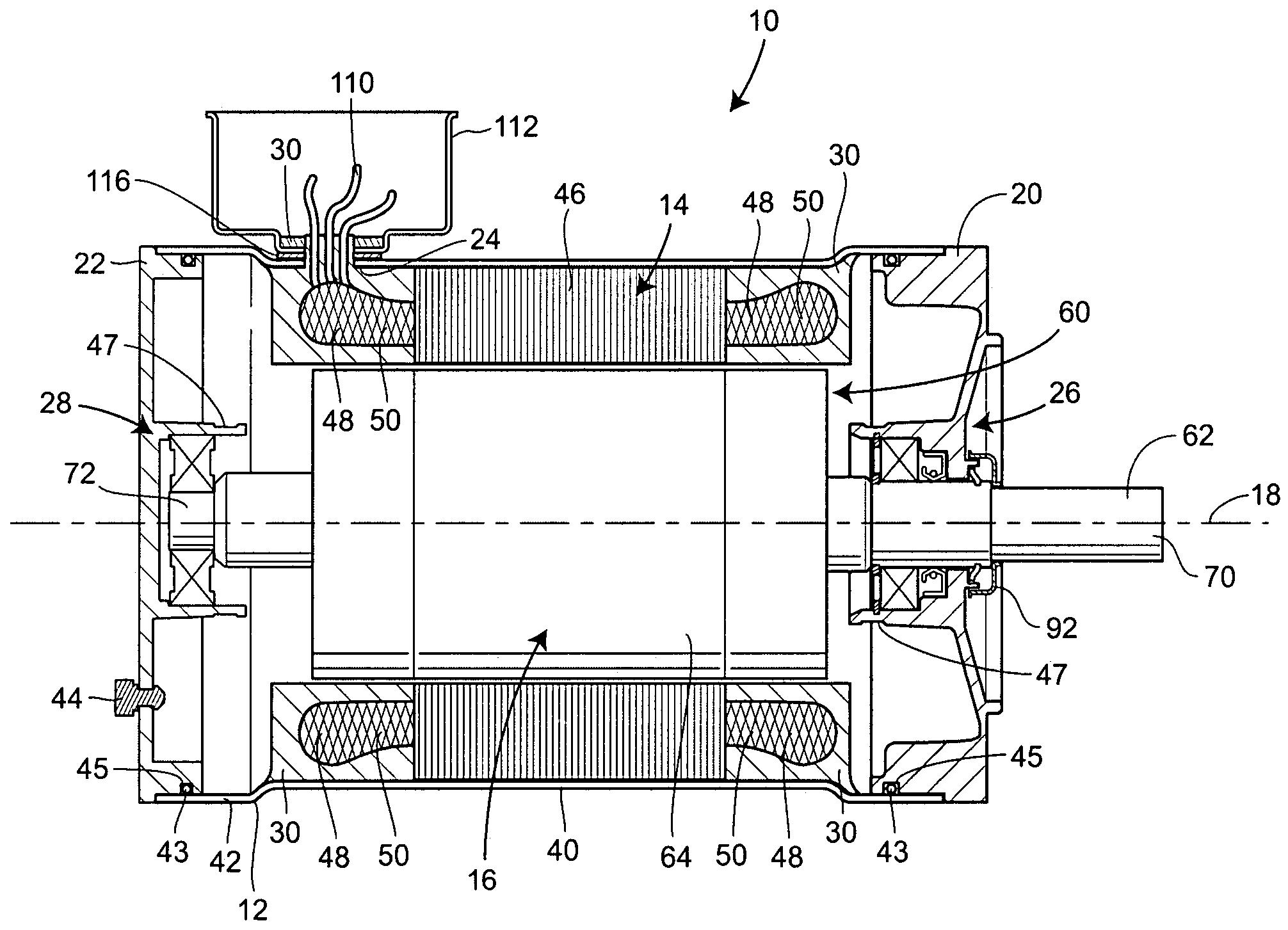
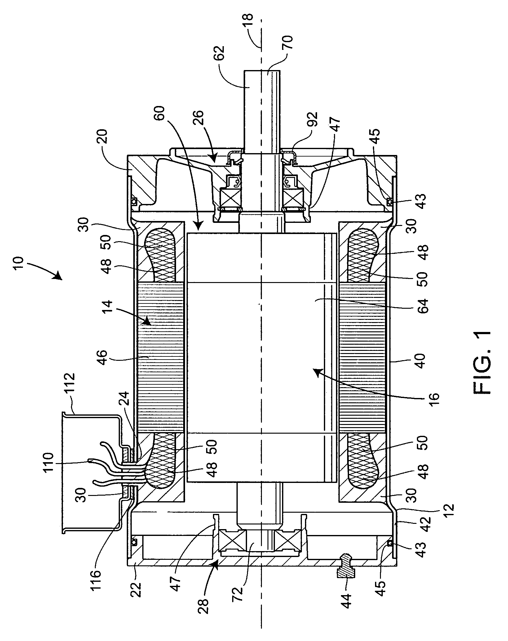
[0025]Referring to FIG. 1, an electric motor 10 constructed in accordance with the teachings of the present disclosure is generally shown. The electric motor 10 includes the basic elements of conventional electric motors that are well known to those of ordinary skill in the art. These components typically include a generally cylindrical motor casing 12 having a central axis 18, a stator assembly 14, a rotor shaft assembly16 disposed on the central axis 18, first and second end bells 20 and 22, respectively, attached to each end of the motor casing 12, and an electrical inlet 24 in the motor casing 12 for supplying power to the motor 10. The motor 10 further includes a first bearing assembly 26 housed in the first end bell 20 and a second bearing assembly 28 housed in the second end bell 22. Both bearing assemblies 26 and 28 support the rotor shaft assembly 16 when rotating about the central axis 18. The motor 10 also includes a heat-conductive solid resin 30 that substantially cover...


PUM


Abstract

An electric motor includes a motor casing, a stator assembly, a rotor shaft assembly, first and second end bells, respectively, attached to each end of the motor casing, and an electrical inlet in the motor casing for supplying power to the motor. The motor further includes a first bearing assembly housed in the first end bell and a second bearing assembly housed in the second end bell. Both bearing assemblies and support the rotor shaft assembly and seal the interior of the motor casing from moisture. The motor also includes a heat-conductive solid resin that encapsulates the stator assembly.

Description

FIELD OF THE INVENTION[0001]The present invention relates generally to electric motors, in particular motors used in applications where they are exposed to high levels of moisture, steam, or chemical solutions. More particularly, the present invention describes an electric motor having features for preventing the ingress of moisture into the motor interior, as well as features for insulating critical motor components from oxidative attack.BACKGROUND OF THE INVENTION[0002]Commercial food processing facilities and the food products moving through such facilities must be maintained in a scrupulously clean condition. One method of achieving this high level of cleanliness is by means of high-pressure, hose-down cleaning with steam, hot water and / or chemical solutions. During the course of the cleaning operation, electric motors utilized in the manufacturing process are exposed to harsh, oxidative conditions. These “washdown motors” as they are referred to in the trade are also used in ch...

Claims


Application Information

Patent Timeline
Patent Type & Authority Patents(United States)
IPC IPC(8): H02K1/04H02K5/00H02K5/10
CPCH02K5/10
Inventor PUTERBAUGH, DAVID K.KOWALCZYK, DAVID F.MARKLEY, KENT J.BROOKS, VERNON
Owner BLUFFTON MOTOR WORKS
Why Eureka
Try Eureka