Signal line driving circuit and image display device
- Summary
- Abstract
- Description
- Claims
- Application Information
AI Technical Summary
Benefits of technology
Problems solved by technology
Method used
Image
Examples
first embodiment
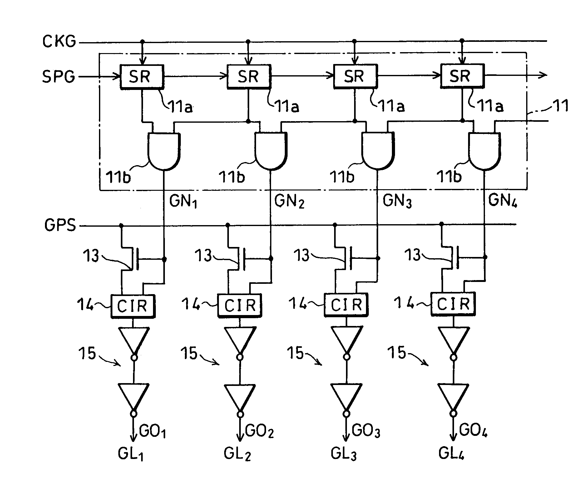
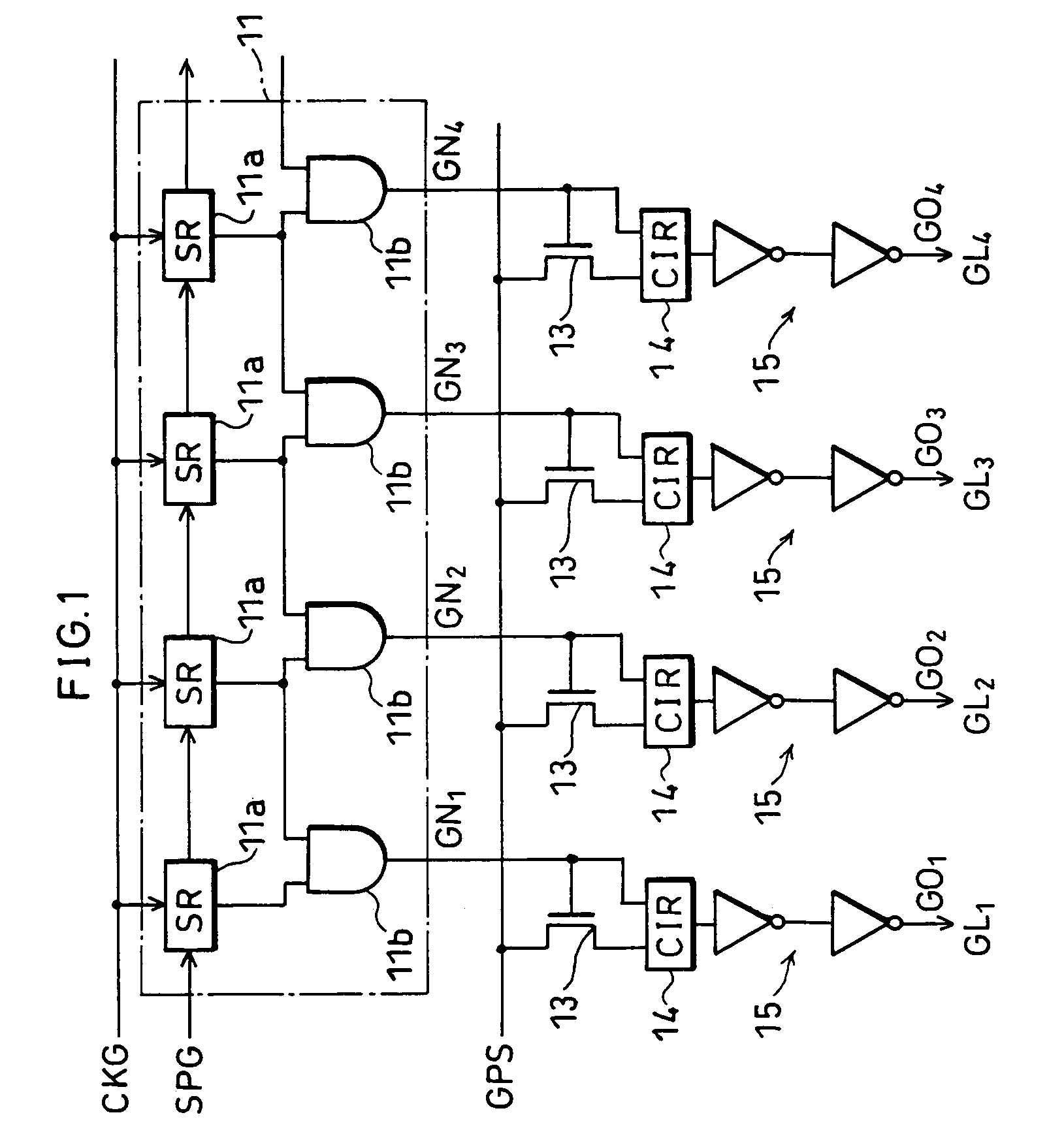
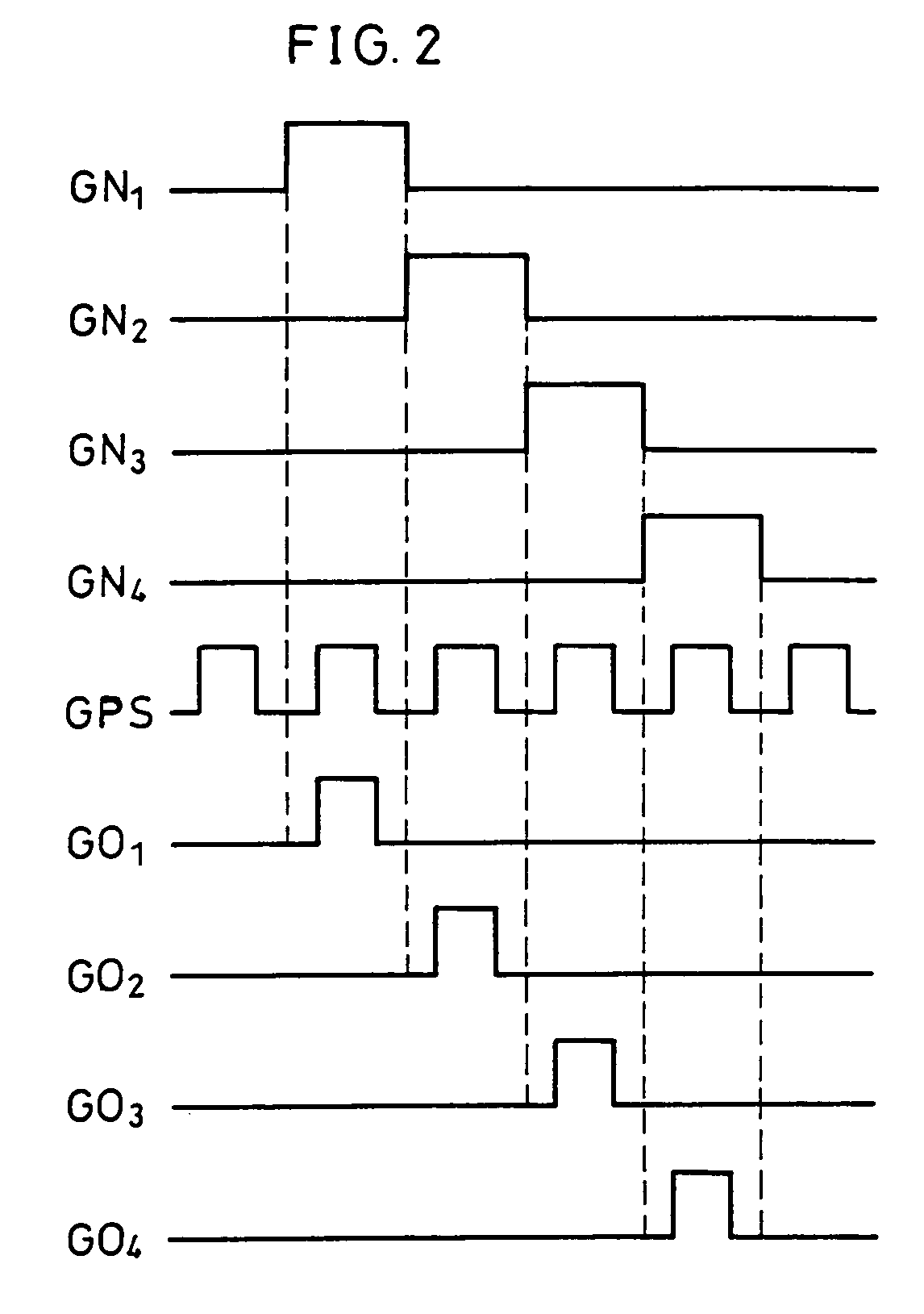
[0039]The following will describe the first embodiment of the present invention with reference to FIGS. 1 and 2.
[0040]As shown in FIG. 1, the signal line driving circuit according to the present embodiment includes a shift register 11, transistors 13, logical operation circuits (CIR as illustrated) 14 and buffer circuits 15.
[0041]The shift register 11 has a plurality of shift circuits 11a and AND gates 11b, of which the shift circuits 11a are serially connected to one another. The shift circuit 11a shifts an externally inputted start pulse SPG subsequently to the shift circuit 11a on the next stage based on a clock signal CKG. The AND gate 11b outputs a logical product of the pulses outputted from two adjacent shift circuits 11a, as the shift pulse GNn (n=1, 2, 3 . . . ).
[0042]Note that, the shift register 11 may exclude the AND gates 11b. In this structure, a pulse outputted from each shift circuit 11a becomes the shift pulse GNn.
[0043]In FIG. 1, the transistor 13 is an n-channel t...
second embodiment
[0050]The following will explain the second embodiment of the present invention with reference to FIG. 3. Note that, for convenience of explanation, in the following embodiments including the present embodiment, the elements having the same or equivalent functions to those already discussed in the first embodiment above will be given the same reference numerals, and explanation thereof will be omitted here.
[0051]The signal line driving circuit in accordance with the present embodiment includes, as shown in FIG. 3, the shift register 11, the transistors 13 and the buffer circuits 15, as with the first embodiment. However, the logical operation circuits 14 are omitted. Specifically, the transistor 13 here is directly connected to the buffer circuit 15 without interference of the logical operation circuit 14.
[0052]With the structure as above, the width specifying pulse GPS is outputted via the transistor 13 while the transistor 13 is ON, i.e. while the shift pulse GNn is active (see FI...
third embodiment
[0056]The following will explain the third embodiment of the present invention with reference to FIG. 4.
[0057]As shown in FIG. 4, the signal line driving circuit in accordance with the present embodiment includes the shift register 11, the buffer circuits 15, as with the signal line driving circuit of the first embodiment (see FIG. 1), except for inverters 21 and transfer gates 22, which are provided instead of the transistors 13 and the logical operation circuits 14.
[0058]The transfer gate 22 is a switching element of a CMOS structure, composed of an n-channel transistor 22a and a p-channel transistor 22b which are connected to each other in parallel. To the gate of the n-channel transistor 22a is inputted the shift pulse GNn, and to the gate of the p-channel transistor 22b is inputted the shift pulse GNn which has been inverted by the inverter 21. Accordingly, the transfer gate 22 becomes ON when the shift pulse GNn is active, and the width specifying pulse GPS is outputted.
[0059]...
PUM
 Abstract
Description
Claims
Application Information
 - R&D
- Intellectual Property
- Life Sciences
- Materials
- Tech Scout
- Unparalleled Data Quality
- Higher Quality Content
- 60% Fewer Hallucinations
Browse by: Latest US Patents, China's latest patents, Technical Efficacy Thesaurus, Application Domain, Technology Topic, Popular Technical Reports.
© 2025 PatSnap. All rights reserved.Legal|Privacy policy|Modern Slavery Act Transparency Statement|Sitemap|About US| Contact US: help@patsnap.com


