Electrical energy from live loads

a technology of electric energy and live loads, applied in the direction of electric generator control, fluid couplings, couplings, etc., to achieve the effect of improving the efficiency of converting pressure energy

Inactive Publication Date: 2006-05-16
NEWMAN EDWIN
View PDF20 Cites 48 Cited by
  • Summary
  • Abstract
  • Description
  • Claims
  • Application Information

AI Technical Summary

Benefits of technology

[0009]A live load is defined in this invention as any load causing variations in pressure through time on the walls of a chamber (a closed pipe) of working fluid. These walls may be impacted through the action of wind, waves, ocean currents, fuel explosion, or moving an automobile over the chamber directly or indirectly, among other causes. Concerning wind and wave action, specific structures are presented to improve the efficiency of converting pressure energy from these sources into electrical energy in a more efficient manner.
[0014]The first aim of the invention is to show how to convert pressure energy into electrical energy. The new structures introduced move minimally, reducing friction loss and increasing system efficiency as will be explained in each preferred embodiment.

Problems solved by technology

These walls may be impacted through the action of wind, waves, ocean currents, fuel explosion, or moving an automobile over the chamber directly or indirectly, among other causes.

Method used


Image

  • Electrical energy from live loads
  • Electrical energy from live loads
  • Electrical energy from live loads

Examples


first preferred embodiment

[0048]FIG. 6 shows an asphalt roadway 47. Buried under the roadway is a stainless steel chamber completely filled with water 49. On top of chamber 49 is stainless steel channel 48 with both legs rested on the top surface of chamber 49. Tube 50 led from chamber 49 is joined to tube 6 to supply pressure variations to Bourdon tube 11 or piston 30. Item 51 denotes the normal underfill of a roadway.

[0049]In operation, as vehicles or people traverse the roadway pressure variations on chamber 49 cause electric power to be produced with minimal displacement of the asphalt.

second preferred embodiment

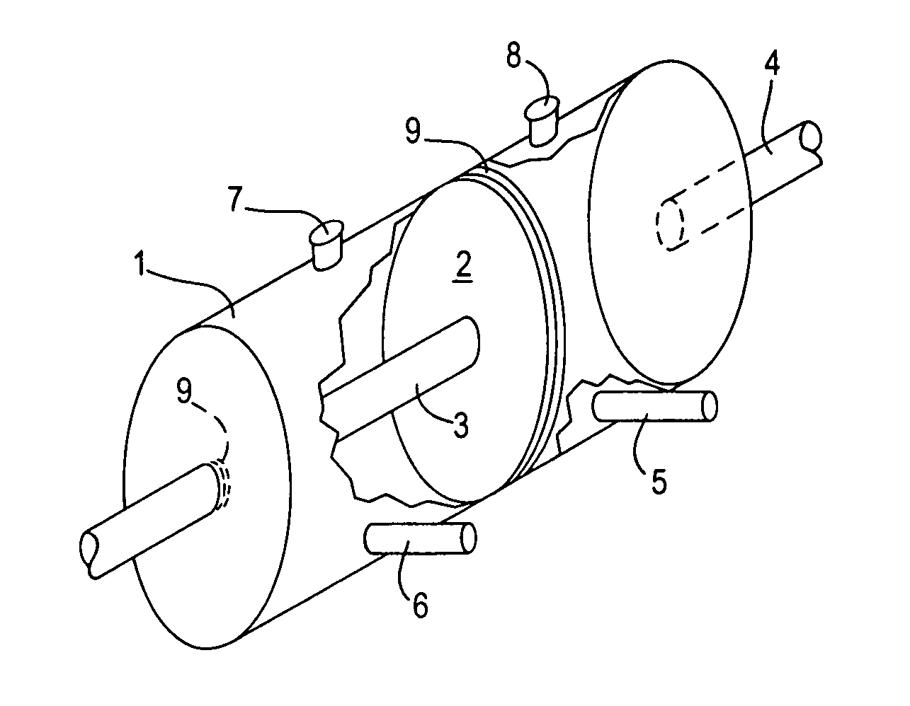
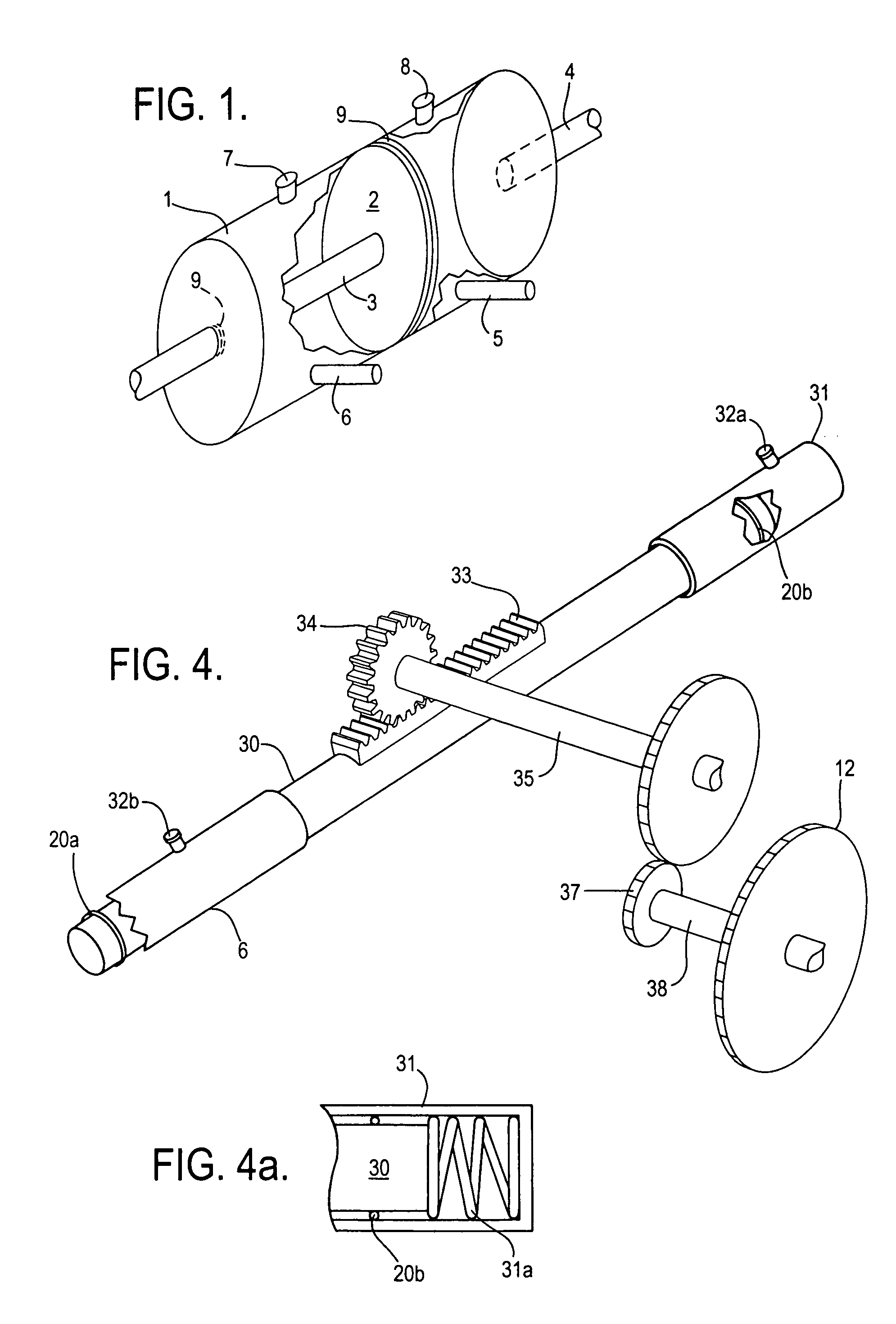
[0050]FIG. 7 shows pole 52 in two sections with rotateable joint 53 between them. Affixed to the upper section is sail 54. The surface of this sail can be painted with a design. Pole 52 is extended a short distance below ground level, shown in FIG. 7a. Concrete form 55 is formed to form a pivot for pole 52 and to contain certain conversion machinery as in FIG. 2, 3 or 4. Joint 56 fixes piston shaft 2 to pole 52 through wall 57. Piston 3 is within water-filled cylinder 1. Exit tubes 5,6 are shown and are led to Bourdon tube 11 and closed pipe 13 as previously noted, or piston 30.

[0051]The wind velocity is always variable unless there is a hurricane. In operation varying pressure on sail 54 causes pole 52 to sway and act as a lever, activating the conversion machinery and producing electricity. Instead of a sail 54, pole 52 may be connected to a tree which would act as a sail 54. See FIG. 18. Another way is to substitute a tall building 58 for sail 54, connecting pole 52 to the top of...

third preferred embodiment

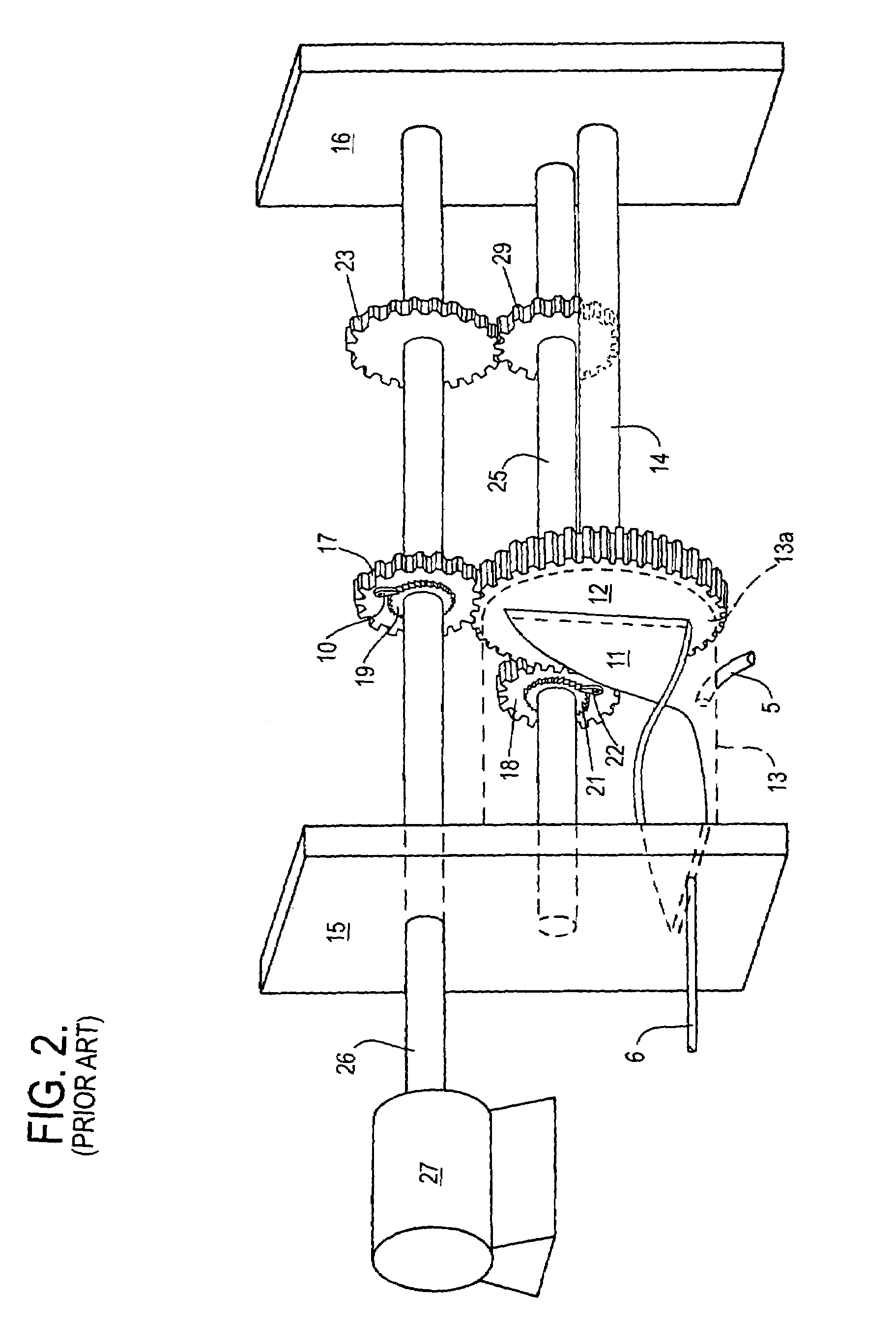
[0053]In FIG. 10 we see a container within a vehicle of some weight 61. This container 61 is enclosed by another container 62 fixedly attached to the framework of a vehicle. Between these containers are a number of structures as in FIG. 1. Shaft 4 is fixedly attached to container 62, and shaft 3 is mace to terminate as a ball bearing 63 which is made to ride on the outer surface of container 61.

[0054]In operation, as the mass of container 61 and its contents acquire a different momentum than the vehicle frame due to the impact of live loads the machinery of the invention is activated to convert pressure energy into electrical energy. The contents of container 61 may be fuel, a battery, or cargo.


PUM


Abstract

A group of devices and machines for converting the mechanical energy of live loads into electricity. A generator is operated by gears which in their turn are operated by a Bourdon tube or similar-acting device fed by working fluid in a pipe from a reservoir. The reservoir walls are impacted by a choice of the rolling weight of a motor vehicle, the bending force on some object and / or by a decompressing force on the working fluid. The invention is applied to roadways, buildings, sailboats, cars with internal combustion engines, elevators, ships and bridges. If the varying impacts are caused by wind or subsurface ocean currents a new type of diverging nozzle is used to magnify pressure input. By using the invention pressure waves are used to transfer energy with minimal movement of working fluid, minimizing friction and other losses.

Description

[0001]Prior applications Ser. No. 10 / 792,148 filed Mar. 4, 2004, Ser. No. 10 / 838,737 filed May 5, 2004 which is a Continuation-In-Part of application Ser. No. 10 / 742,983, filed Dec. 23, 2003, and Ser. No. 10 / 872,596 filed Jun. 22, 2004 are abandoned. This application is a Continuation-In-Part of the above applications.BACKGROUND[0002]1. Field of the Invention[0003]This invention concerns converting pressure variations into electrical energy through the agency of hydraulic and / or mechanical devices and more particularly concerns the various causes or pressure variations and how their energy may be more efficiently converted into electrical energy.[0004]2. Prior Art[0005]Piezoelectric inventions convert pressure variations directly into electrical energy but their efficiency is very low and charging piezoelectric material is expensive.[0006]Bourdon tubes that transmit power have been proposed. See my U.S. Pat. No. 6,781,253. But the use of the invention is restricted to surface and su...

Claims


Application Information

Patent Timeline
Patent Type & Authority Patents(United States)
IPC IPC(8): F16D31/02
CPCF03G7/10
Inventor NEWMAN, EDWIN
Owner NEWMAN EDWIN
Why Eureka
Try Eureka