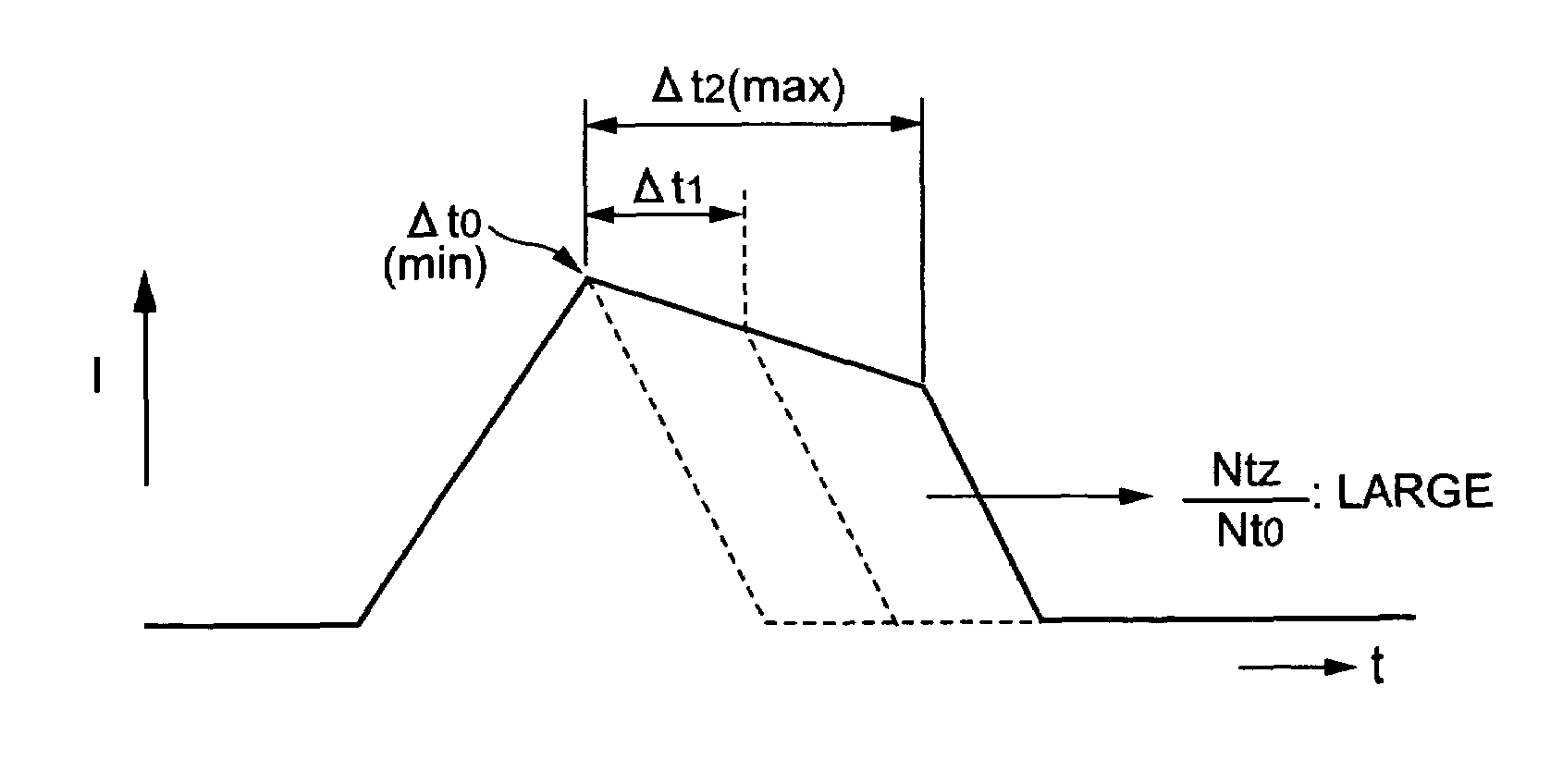
Machining power supply for wire electrical discharge machine
a technology of electrical discharge machine and power supply, which is applied in the direction of metal-working equipment, manufacturing tools, electrical-based machining equipment, etc., can solve the problems of easy over-extension of the breakage limit of the wire electrode, inability to perform fine energy control, and inability to control the pulse waveform of the electric current according to the pulse waveform, etc., to achieve the effect of increasing the pulse width of the trapezoidal wave current, increasing the pulse width and increasing the pulse width
- Summary
- Abstract
- Description
- Claims
- Application Information
AI Technical Summary
Benefits of technology
Problems solved by technology
Method used
Image

Examples
embodiment 2
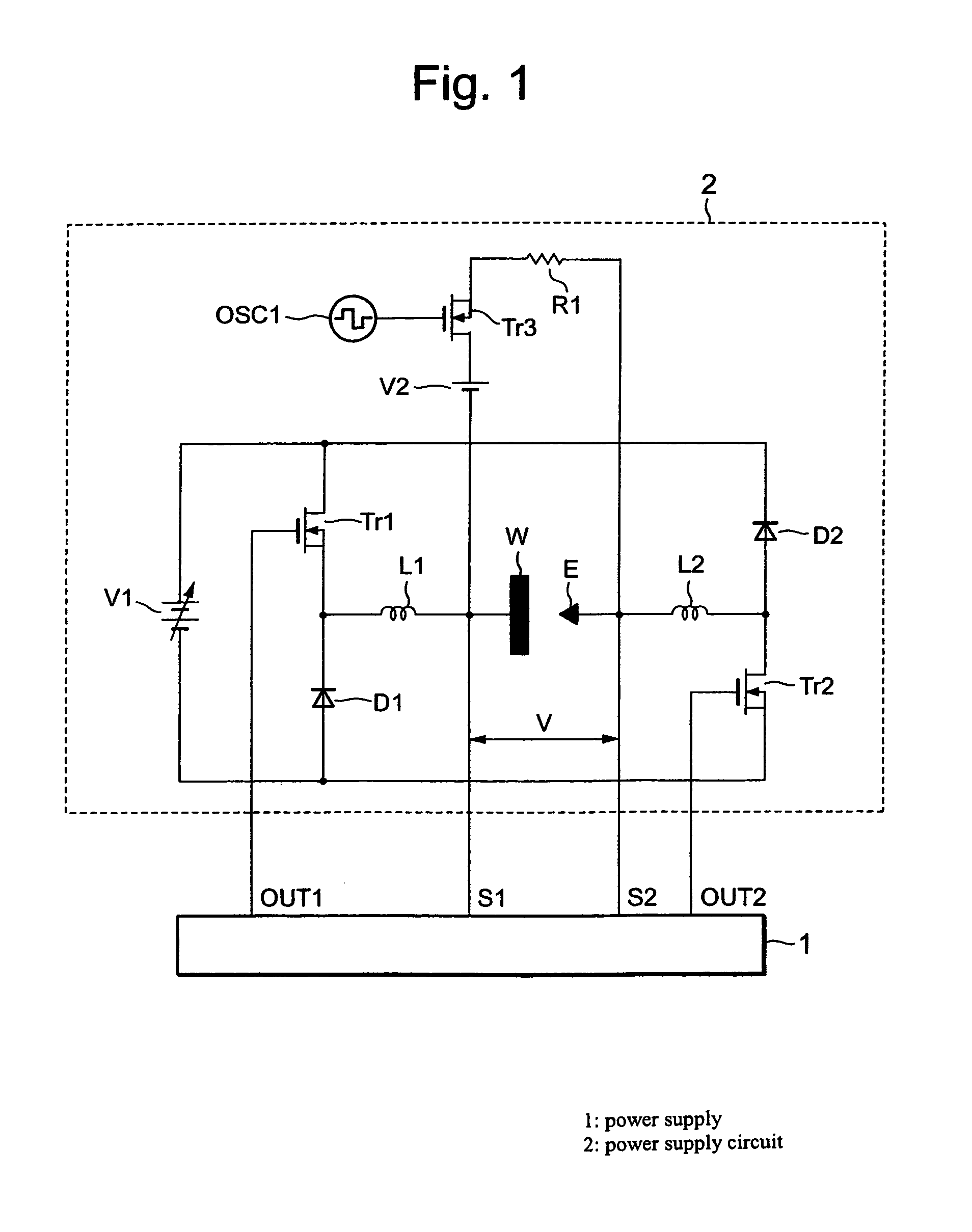
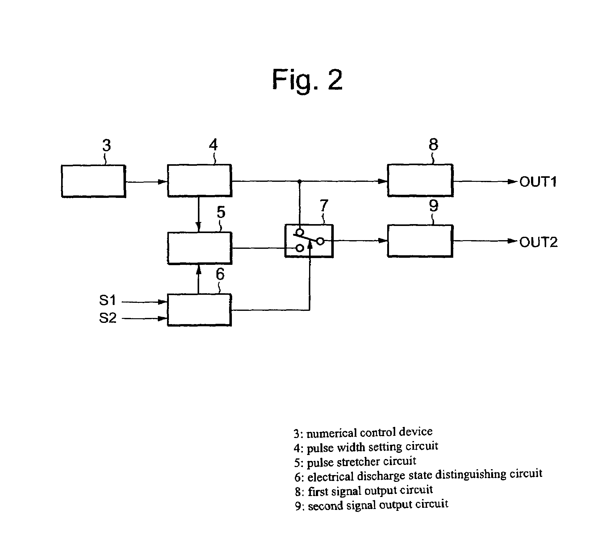
[0041]FIG. 6 is a configuration diagram of the machining power control circuit 1 of the machining electrical power supply device for the wire electrical discharge machining apparatus related to Embodiment 2 of this invention, and the machining electrical power supply circuit 2 is similar to FIG. 1 of Embodiment 1.
[0042]In FIG. 6, reference numeral 3 is a numerical control device, 5a is a pulse stretcher circuit, 6 is an electrical discharge state distinguishing circuit, 16 is a clock generator, 17a is a first counter, 17b is a first pulse agreement comparator circuit, 17c is a first pulse width setting circuit, 18a is a second counter, 18b is a second agreement comparator circuit, 18c is a second pulse width setting circuit, 19a is an OFF counter, 19b is an OFF counter agreement comparator circuit, 19c is an OFF time setting circuit, 20, 21 and 22 are latches, 23, 24 and 25 are flip-flops, OUT1 is an ON-OFF operator drive signal for a switching element Tr1 of the machining electrica...
embodiment 3
[0056]FIG. 8 is a configuration diagram of the machining electrical power supply control circuit 1 of the machining electrical power supply device for the wire electrical discharge machining apparatus according to Embodiment 3 of this invention, and the machining electrical power supply circuit 2 is similar to FIG. 1 of Embodiment 1. Further, numerical references identical to FIG. 2 of Embodiment 1 indicate identical or equivalent parts.
[0057]In FIG. 8, numerical reference 26 is a pulse stretcher range setting circuit, 27 is an all-waveforms output counter means for counting the output count of all waveforms, 28 is a trapezoidal wave output counter means for counting the output count of trapezoidal waves only, 29 is a reset circuit for resetting counter values at an optional cycle, 30 is a counting circuit for performing calculations according to the output of the all-waveforms output counter means 27 and the trapezoidal wave output counter means 28.
[0058]OUT1—the output signal of t...
embodiment 4
[0064]FIG. 10 is a configuration diagram of the machining electrical power supply control circuit 1 of the machining electrical power supply device for the wire electrical discharge machining apparatus according to Embodiment 4 of this invention, and the machining electrical power supply circuit 2 is similar to FIG. 1 of Embodiment 1. Further, numerical references identical to FIG. 8 of Embodiment 3 illustrate identical or equivalent parts. In FIG. 10, reference numeral 31 is a triangular wave output counter means for counting the triangular wave output count only, 32 is a computation circuit for carrying out computations according to the output of the all-waveforms output counter means 27 and the triangular wave output counter means 31.
[0065]By calculating the all-waveforms output-count that is output from the all-waveforms output-count means 27 and the trapezoidal-wave-only output-count that is output from the trapezoidal wave output-count means 28, the output count of the triangu...
PUM
| Property | Measurement | Unit |
|---|---|---|
| clock frequency | aaaaa | aaaaa |
| frequency | aaaaa | aaaaa |
| electrical power | aaaaa | aaaaa |
Abstract
Description
Claims
Application Information