Vertical cavity laser producing different color light

a vertical cavity laser and color light technology, applied in semiconductor lasers, active medium materials, instruments, etc., can solve the problems of loss of contrast ratio, and loss of overall display efficiency, so as to achieve the effect of increasing light leakage, not decreasing contrast ratio, and loss of contrast ratio

Inactive Publication Date: 2006-05-16
EASTMAN KODAK CO
View PDF5 Cites 15 Cited by
  • Summary
  • Abstract
  • Description
  • Claims
  • Application Information

AI Technical Summary

Benefits of technology

[0019]It is an advantage of the present invention to use a blue emitting, planar, large area, two-dimensional vertical cavity surface emitting laser (VCSEL) array as the light source for a liquid crystal display. Each blue colored element contains thousands of micron-sized laser pixels, which are mutually incoherent. This leads to each blue colored element producing multimode laser light. As a result of the pixel size being 3 to 5 microns in diameter, the divergence angle of the multimode laser light is on the order of 3–5°. This small divergence angle enables a 1:1 correspondence between the laser's blue colored elements and the pixels of the liquid crystal display. Correspondingly, it is no longer necessary to include the color filter array as one of the LCD film components.
[0020]In order to produce red and green light, a color converter layer is placed directly above the light switch. As such, the blue laser light is selectively absorbed by the converter, which down-converts the blue laser light into red and green light at the locations of the red and green display pixels.
[0021]An additional feature of the near collimation of the light source is that the liquid crystal viewing angle compensation films can be removed from the display structure. By including a birefringent layer as one of the VCSEL components, the multimode laser light output from the two-dimensional vertical cavity laser array can be polarized preferentially along one direction. As a result of the light source producing polarized light, the bottom polarizer element and its associated reflective polarizer element can be limited from the present LCD invention. It is also common to include collimating films as part of the LCD components; however, these films can be removed since the laser output from the two-dimensional vertical cavity laser array is naturally collimated (3–5° divergence angle).
[0022]An additional advantage of the present invention comes from the light output from each blue colored element being nearly single wavelength. This property permits the dark state of the liquid crystal display to be extremely efficient. Typically, a liquid crystal display's dark state is optimized at one wavelength with increasing light leakage at other wavelengths. The chromatic dark state contributes to loss of contrast ratio. Since only blue light is incident on the liquid crystal light shutter, the contrast ratio is not decreased due to chromatic losses.

Problems solved by technology

Correspondingly, this absorption of light outside of each pixel's transmission spectra results in a loss of overall display efficiency.
However, not all of the light of the undesired polarization is recycled and not all of the recycled light exits the BLU with the correct polarization state.
As a result, an unpolarized BLU light source results in nearly a factor of two efficiency loss upon passing through the bottom polarizer.
However, LCD's suffer from poor contrast ratios at larger viewing angles.
Unless the contrast ratio is improved at large viewing angles, the penetration of LCDs into certain markets will be limited.
The poor contrast ratio is typically due to increased brightness of the display's dark state.
However, these methods improve the hue shift and contrast ratio only slightly and for a limited viewing cone.
Also, the manufacturing of compensation films and multi-domain liquid crystal cells is typically expensive, thus increasing the overall cost of the display.
Also, the PL-LCD light source is much less efficient than the standard cold cathode fluorescent lamps (CCFLs) used in typical LCD displays.
As discussed above, these drawbacks are loss of efficiency (due to unpolarized backlights and usage of CFA's), poor color gamut, and loss of contrast and color at larger viewing angles.
OLED displays overcome some of these disadvantages, however, they currently suffer from short lifetimes and higher manufacturing costs.
Part of the higher manufacturing cost is inherent in the OLED design, such as the need to pixelate the OLED emitter region and the greater complexity of thin film transistors (TFTs) for current driven devices.

Method used


Image

  • Vertical cavity laser producing different color light
  • Vertical cavity laser producing different color light
  • Vertical cavity laser producing different color light

Examples


Embodiment Construction

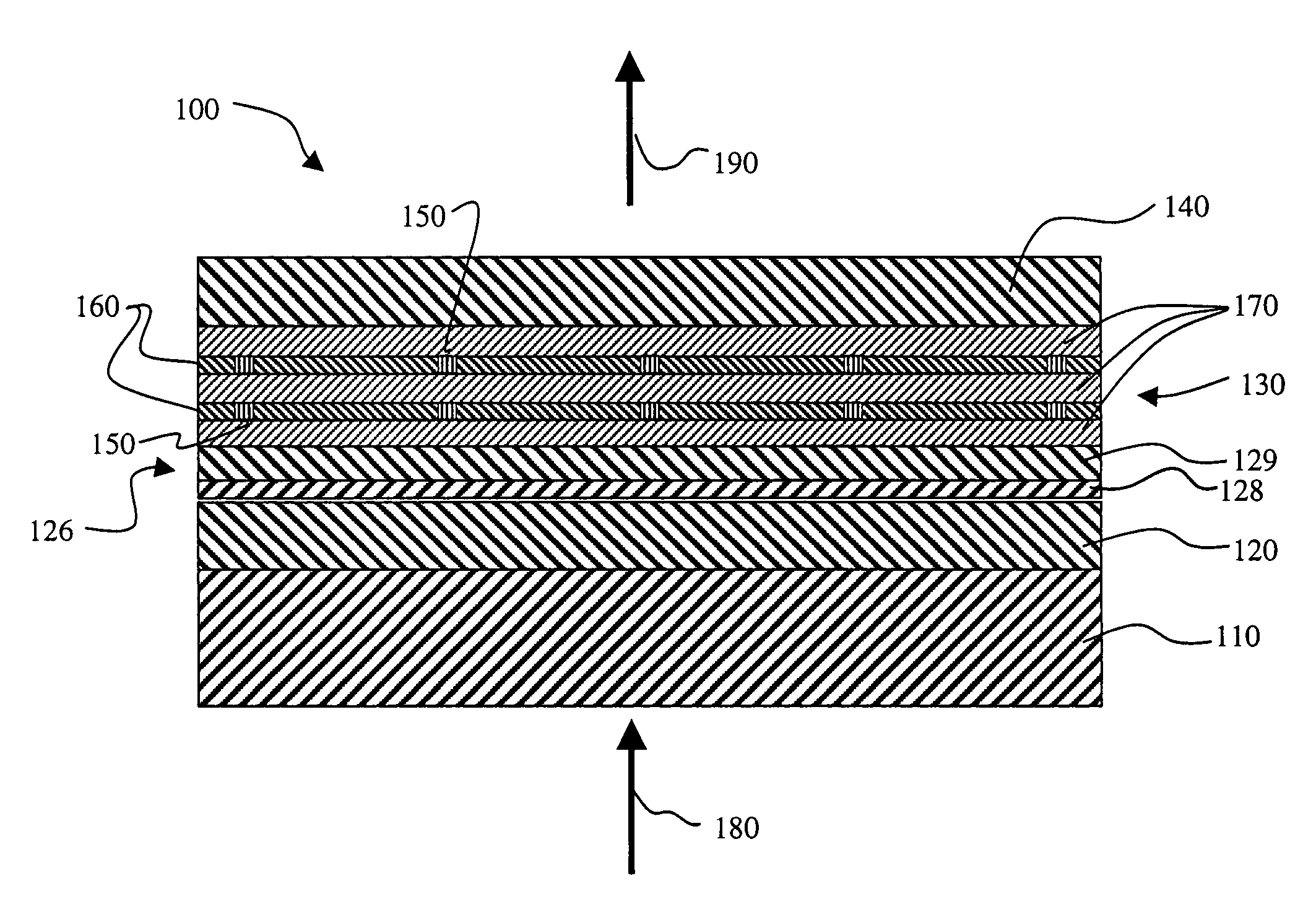
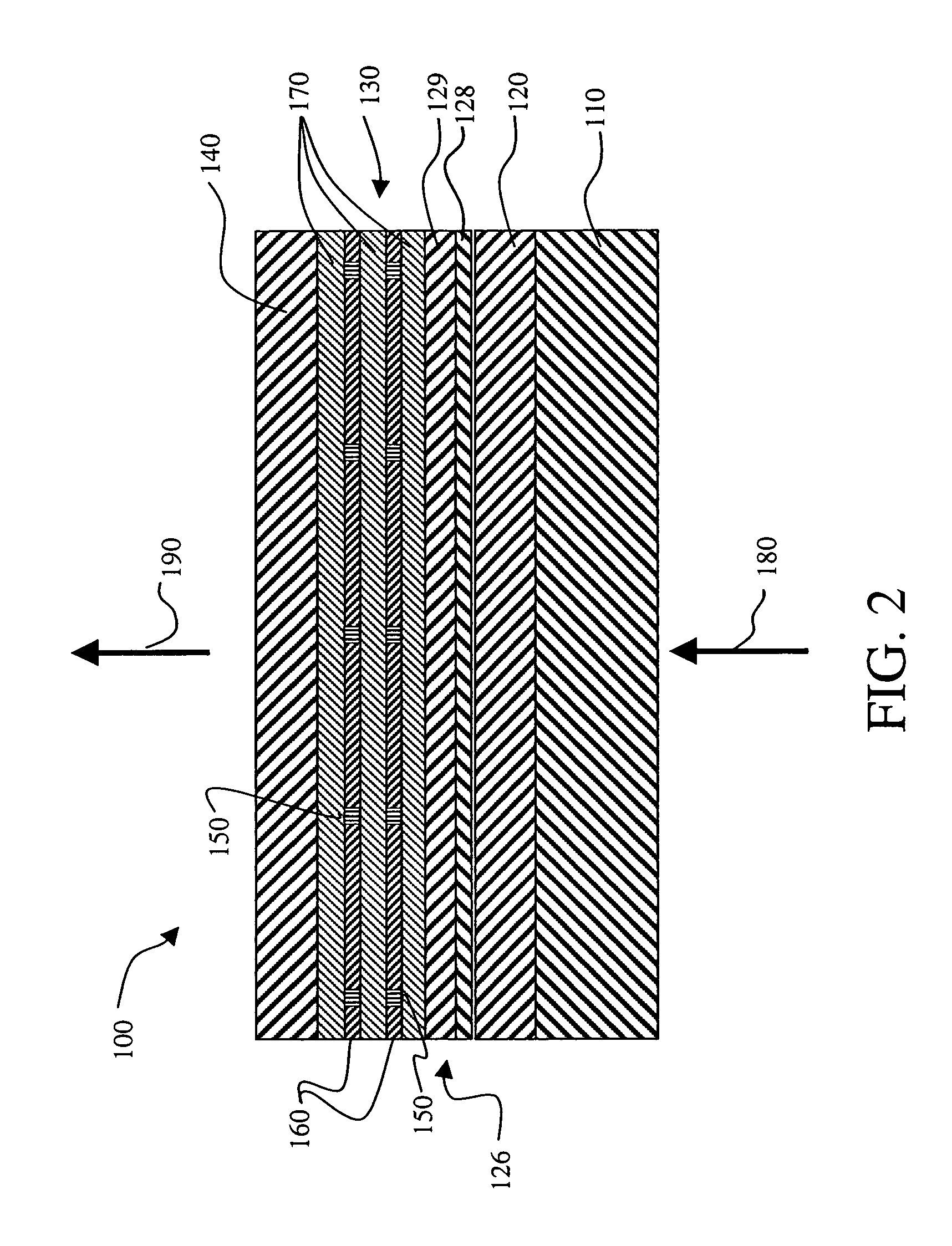
[0037]The invention is enabled by a large planar light source that produces blue light which is nearly collimated and single wavelength. A light source that meets these criteria is a two-dimensional vertical cavity surface emitting laser (VCSEL) array device 100, as shown schematically in FIG. 2. FIG. 3 shows a top view of the two-dimensional VCSEL array device 100 where on the surface of the VCSEL needs to be defined blue emitting elements 205 which are composed of thousands of micron-sized laser pixels 200 separated by interpixel regions 210. In order to obtain large area blue laser light emission, it is preferred that an active region 130 be composed of organic-based gain media. However, recent research, R. N. Bhargava, Phys. Stat. Sol. 229, 897 (2002), points to the possibility of obtaining visible wavelength emission from inorganic-based nanoparticles. Examples of these are ZnO nanoparticles (with preferred diameters less than 10 nm) either undoped or doped with impurities, suc...


PUM

PropertyMeasurementUnit
sizeaaaaaaaaaa
tilt angleaaaaaaaaaa

Abstract

A display apparatus for producing colored pixelated light includes a backlight unit for producing pump-beam light and a vertical cavity laser array device including a structure for modulating the properties of the device at spaced locations so as to provide an array of spaced laser pixels which have higher net gain than the interpixel regions, and an active region which produces blue light in response to the pump-beam light. The apparatus also includes a light shutter and a color conversion layer including different portions, where selected different portions in response to blue light produce a different colored light and being adapted to increase the angular cone of view of the selected colored light.

Description

CROSS REFERENCE TO RELATED APPLICATIONS[0001]Reference is made to commonly assigned U.S. patent application Ser. No. 10 / 864,100 filed simultaneously herewith by Keith B. Kahen, et al., entitled “Display Device Using Vertical Cavity Laser Arrays”, the disclosure of which is herein incorporated by reference.FIELD OF THE INVENTION[0002]The present invention relates to a display device for producing colored light which uses a vertical cavity laser array.BACKGROUND OF THE INVENTION[0003]In order to facilitate reading of the specification, the following terms are defined. Optic axis herein refers to the direction in which propagating light does not see birefringence. Polarizer and analyzer herein refer to elements that polarize electromagnetic waves. However, the one closer to the source of the light will be called a polarizer, while the one closer to the viewer will be called an analyzer. Polarizing elements herein refers to both the polarizer and analyzer. Azimuthal angle φ and tilt ang...

Claims


Application Information

Patent Timeline
Patent Type & Authority Patents(United States)
IPC IPC(8): H01L21/00H01L33/00H01S3/03H01S3/09G02F1/13357H01S5/42H04N9/31
CPCG02F1/133617
Inventor KAHEN, KEITH B.MONTBACH, ERICA N.
Owner EASTMAN KODAK CO
Why Eureka
Try Eureka