Surface inspection system

a surface inspection and system technology, applied in the field of surface inspection systems, can solve the problems of insufficient light amount necessary for the surface inspection system, limitation of the increase of the projected light intensity, and low light emission amount, so as to improve the inspection accuracy, the effect of improving throughput and sufficient projected light intensity

Inactive Publication Date: 2006-05-16
KK TOPCON
View PDF10 Cites 14 Cited by
  • Summary
  • Abstract
  • Description
  • Claims
  • Application Information

AI Technical Summary

Benefits of technology

[0016]It is an object of the present invention to provide a surface inspection system, by which it is possible to provide sufficient projected light intensity and which contributes to the improvement of inspection accuracy and to the improvement of throughput. It

Problems solved by technology

However, in case the laser diode is used as the light emitting source, despite of the fact that the laser diode has various advantages such as easiness to handle, safety and longer service life, there is such problem that it has lower light emission amount compared with the gas laser, etc., and there is a limitation to the increase of the projected light intensity.
However, compared with a red laser diode, etc., the blue laser diode has further lower light emission amount, and it has such problem that enough light amount necessary for the surface inspection system can not be provided.
However, if the

Method used


Image

  • Surface inspection system
  • Surface inspection system
  • Surface inspection system

Examples


second embodiment

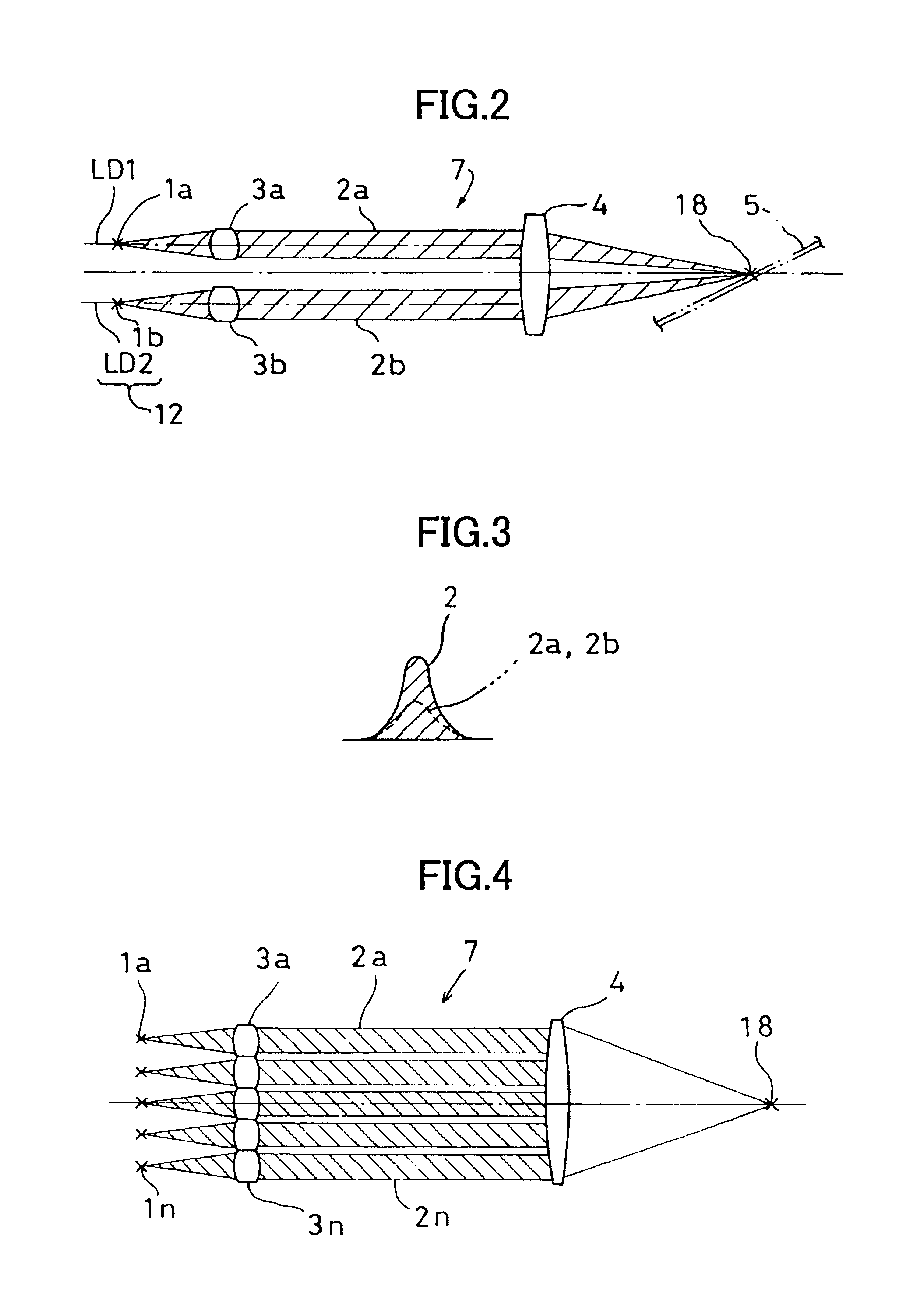
[0061]FIG. 4 shows the present invention where a multiple of light emitting sources 1a, . . . 1n are used.

[0062]It is designed in such manner that collimator lenses 3a, . . . 3n are provided to the light emitting sources 1a, . . . 1n respectively so that laser beams 2a, . . . 2n are projected to a single image forming lens 4 via the collimator lenses 3a, . . . 3n respectively. Optical axes of the collimator lenses 3a, . . . 3n are made parallel to an optical axis of the image forming lens 4.

[0063]In this embodiment, all of the laser beams 2a, . . . 2n are converged to a single projecting point 18. As shown in FIG. 5, the intensity of the projected light at the projecting point 18 is about “n” times as high as the light intensity of a single light emitting source 1. In FIG. 5, light intensity is represented on an axis of ordinate, and space is represented on an axis of abscissa.

[0064]In FIG. 4, a plurality of the light emitting sources 1 are arranged in a single column, while these m...

third embodiment

[0070]In case there are three or more light emitting sources 1 in the third embodiment as described above, the light emitting sources 1 and the collimator lenses 3 should be arranged at positions along a radial line having its center on the optical axis of the image forming lens 4.

fourth embodiment

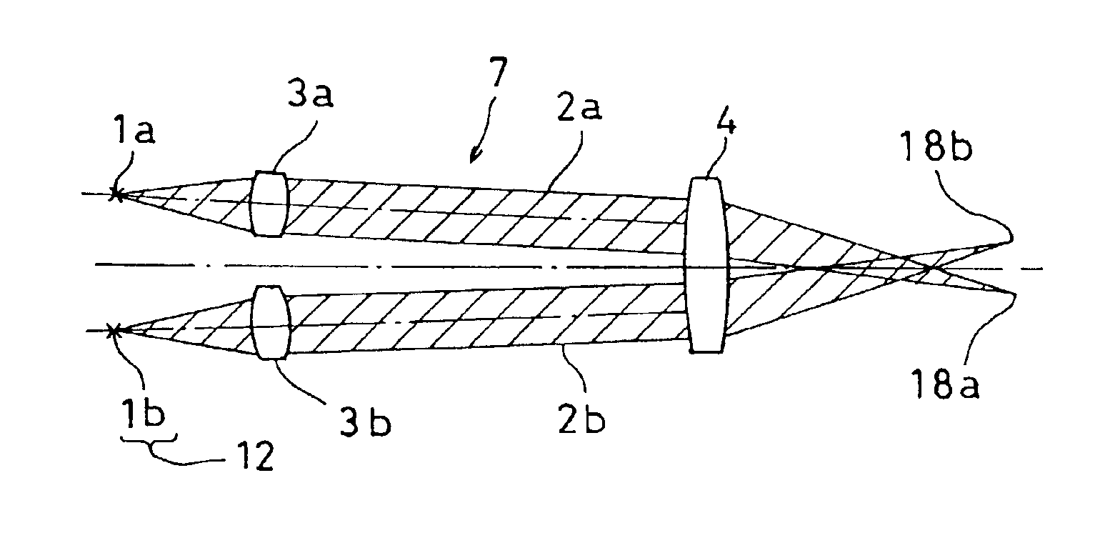
[0071]Next, FIG. 7 is a drawing to show a fourth embodiment, in which an optical axis of a collimator lens 3 is tilted with respect to the optical axis of the image forming lens 4.

[0072]When the optical axis of the collimator lens 3 is tilted with respect to the optical axis of the image forming lens 4, the projecting point 18 is moved. Therefore, if the optical axis of each of the collimator lenses 3a and 3b is tilted, projecting points 18a and 18b of the light beams from the light emitting sources 1a and 1b are deviated from each other.

[0073]The distribution of light intensity of the projected light at the projecting point 18 under the optical conditions shown in FIG. 8 is turned to the synthesized light intensity distribution of the laser beams 2a and 2b shown in FIG. 9, and it is approximately in trapezoidal form as shown by a solid line in the figure. In this case, if it is assumed that the necessary projected light intensity is I and a pitch of scanning is obtained, it is p′ a...


PUM


Abstract

A surface inspection system for projecting a laser beam to a surface of a substrate and for detecting a foreign object by detecting scattered reflection light of the laser beam, comprising a light source unit having a plurality of light emitting sources for emitting the laser beams, and a projecting optical system for projecting the laser beam from each of the light emitting sources to the surface of the substrate.

Description

BACKGROUND OF THE INVENTION[0001]The present invention relates to a surface inspection system for inspecting a very small foreign object or a very small flaw such as a crystal defect on a surface of a substrate such as a semiconductor wafer.[0002]A surface inspection system is used for detection of a foreign object or a flaw on a surface of a substrate by projecting a laser beam on the surface of the substrate and by detecting scattered reflection light caused by the foreign object or the flaw. As a light emitting source for the surface inspection system, means such as a gas laser (He, Ar, etc.) has been used in the past. In recent years, a laser diode (LD) is used because of easiness to handle, safety, and longer service life, etc.[0003]FIG. 27 represents a conventional type projecting optical system, using the laser diode as the light emitting source.[0004]A laser beam 2 emitted from a light emitting source 1 is turned to a parallel beam by a collimator lens 3, and the beam is con...

Claims


Application Information

Patent Timeline
IPC IPC(8): G01N21/00G01N21/95H01L21/66
CPCG01N21/9501G01N21/8806H01L22/00
Inventor ISOZAKI, HISASHIENOMOTO, YOSHIYUKI
Owner KK TOPCON
Why Eureka
Try Eureka