Method for processing in situ inspection reformer tube data

a technology of reformer tubes and data processing, applied in the field of in situ inspection of reformer tubes, can solve the problems of corrosive substances, frequent pressure changes of tubes, and significant replacement costs of tubes, and achieve the effects of preventing tube failure, huge potential, and optimizing production

Inactive Publication Date: 2006-05-16
QUEST INTEGRITY USA LLC
View PDF11 Cites 15 Cited by
  • Summary
  • Abstract
  • Description
  • Claims
  • Application Information

AI Technical Summary

Benefits of technology

[0017]With present technology a 15-meter tube can be inspected within three minutes. An inspection such as this will provide over 1,000,000 radius readings. The method provides means to compress this information to allow easy manipulation and analysis.
[0019]The use of the internal laser mapping technique is not only useful in preventing tube failure but has huge potential in optimizing production from the whole tube set without sacrificing reliability.

Problems solved by technology

These tubes represent a significant cost for replacement and can be a major source of plant unavailability if unplanned failures occur.
Such tubes are frequently subjected to pressure changes and contact with corrosive substances.
Under such situations creep, metal dusting, and surface irregularities frequently develop.
If left untreated, creep will develop into cracks that will propagate leading to failure of the tube.
The plant operator is faced with balancing production needs against tube life and risk of tube failure.
One of the major concerns in plant operation is that the reformer tubes operate at an elevated temperature such that they are susceptible to a failure mechanism referred to as “creep”.
However, with the trend towards larger tube diameters and longer intervals between turnarounds, the detection of such defects may not allow for sufficient time for forward planning of tube replacements.
Also, such “end of life” techniques do not allow any differentiation between the “good” tubes.
Typically, destructive testing is used on a small number of tubes removed from the reformer to try and determine the absolute life remaining.
Whatever the method is used, the results are used on a sample size that is not statistically valid.
Another problem that can occur in reformer tubes is metal dusting.
Metal dusting is a condition where the process stream attacks the interior of the reformer tube with subsequent, significant metal loss.
This can be severe enough to be the life limiting condition for the tube.
External diameter measurements have been used but they are limited as the automated devices only measure across one diameter and are often access-restricted by tube bowing.
Manual measurements are too time consuming to provide more than a few readings per tube.
No external measurement method can provide diameter growth data at or through the reformer refractory.
External measurements are inherently less precise as they are based on a cast surface rather than the internal machined surface and do not take into account the effects of oxide shedding.

Method used


Image

  • Method for processing in situ inspection reformer tube data
  • Method for processing in situ inspection reformer tube data
  • Method for processing in situ inspection reformer tube data

Examples


Embodiment Construction

[0029]Reference will now be made in detail to the present embodiments of the invention, examples of which are illustrated in the accompanying drawings. Wherever possible, the same reference numbers will be used throughout the drawings to refer to the same or like parts (elements).

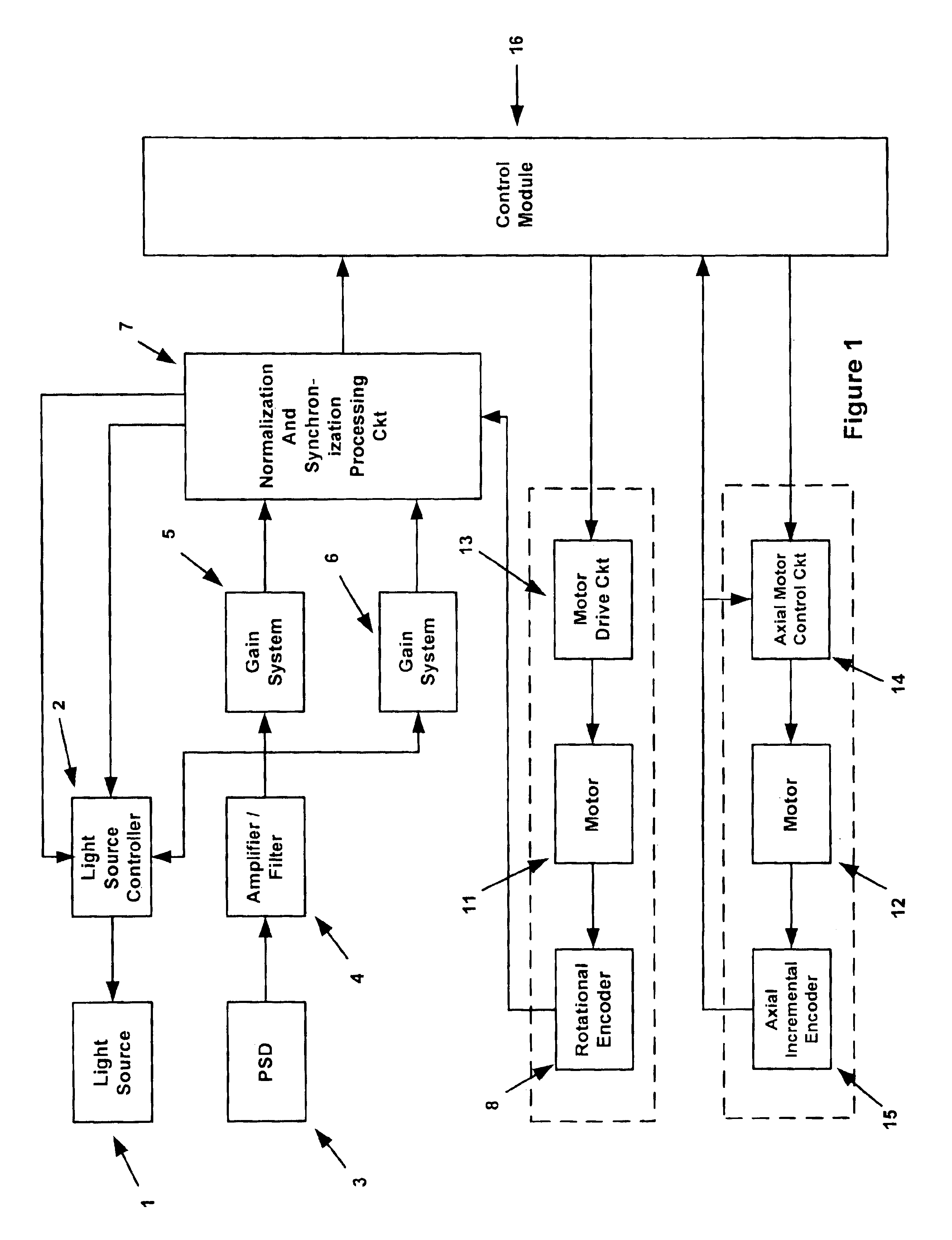
[0030]FIG. 1 is a block diagram of an embodiment of the invention. Components may be either hardware components or software modules as described below. The probe includes a light source 1.

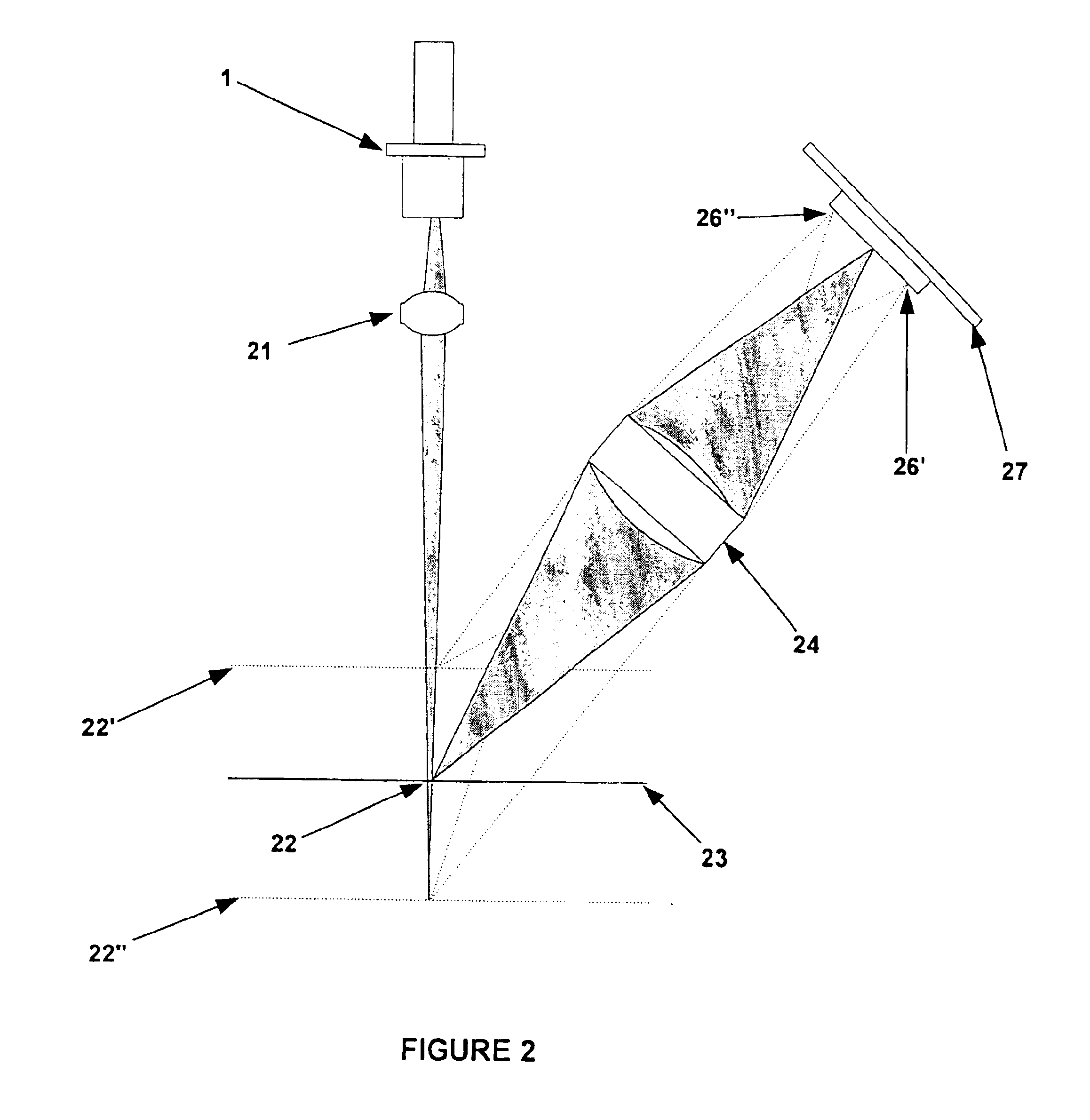
[0031]The purpose of the light source 1 is to project a spot of light on the surface (not shown) to be inspected. Light source 1 is typically a laser diode or light emitting diode (LED). A light source controller 2 is connected to light source 1. Controller 2 sets and controls the optical power level of light source 1. The power level may either be fixed or varied to produce a preset signal level.

[0032]A position sensitive photo detector (PSD) 3 is situated so as to detect the spot made by light source 1. Photo detector 3 ...


PUM

PropertyMeasurementUnit
Inner Diameteraaaaaaaaaa
access timeaaaaaaaaaa

Abstract

The present invention relates to a method for processing a signal obtain, from an in situ reformer tube inspection, that includes X, Y, and intensity data sets for each pixel of a sensor from an image sensor receiving a substantially ring shaped image. The method converts a signal having an X position, a Y position, and an intensity component to a signal having an angle, a radius, and an intensity and filtering out all signal sets that do not have a radius greater than a predetermined radius.

Description

CROSS REFERENCE TO RELATED APPLICATIONS[0001]This application is a divisional of and claims the benefit of U.S. Non-Provisional Application Ser. No. 09 / 713,415 filed Nov. 15, 2000 under 35 U.S.C.§120.[0002]The present patent application is related to our co-pending application entitled “A Method For Reformer Tube In Situ Inspection Radius Calculation,” U.S. application Ser. No. 10 / 707,630 filed Dec. 25, 2003, which is incorporated by reference as if fully set forth herein.BACKGROUND OF INVENTION[0003]1. Field of the Invention[0004]The present invention relates to inspection of materials, and more particularly to the inspection of the surface of materials for creep, metal dusting, irregularities, and manufacturing flaws. With still greater particularity the invention pertains to the inspection of the interior of cylindrical surfaces such as reformer tubes used in chemical processing.[0005]2. Description of the Related Art[0006]Reformer tubes are used in many chemical processes. Examp...

Claims


Application Information

Patent Timeline
Patent Type & Authority Patents(United States)
IPC IPC(8): G01N21/00G01N21/954G06T7/00
CPCG01N21/954G06T7/0004G06T2207/30164
Inventor BONDURANT, PHILLIP D.
Owner QUEST INTEGRITY USA LLC
Why Eureka
Try Eureka