Multiple plate tip or sample scanning reconfigurable scanned probe microscope with transparent interfacing of far-field optical microscopes

a probe microscope and multi-plate tip technology, applied in the direction of mechanical measuring arrangement, mechanical roughness/irregularity measurement, instruments, etc., can solve the problems of limited patent application, affecting the characteristics of tuning forks, and very limited invention of karrai and hines

Inactive Publication Date: 2006-05-23
NANONICS IMAGING LTD
View PDF7 Cites 9 Cited by
  • Summary
  • Abstract
  • Description
  • Claims
  • Application Information

AI Technical Summary

Benefits of technology

[0016]The ultra-thin SPM microscope that results from the present invention incorporates the first tip scanning system that can be placed on any optical microscope upright or inverted. It is the first SPM that permits tip or sample scanning in the same instrument and that can be switched from an AFM mode of operation where the tip is in non-contact or intermittent contact with the sample to a contact mode of operation where the tip is in contact all the time with the sample. It is also the first tip or sample scanning system that permits all the lenses of an upright optical microscope to be rotated freely during SPM operation, and is the first SPM that permits two independently controlled tips to be brought in contact with a sample. The invention readily allows the microscope to be inserted into an optical or other cryostat for low temperature operation with one or all of the features noted above. It can also be used for confocal optical microscopy and can work with accessories that permit operation in a liquid environment.

Problems solved by technology

This patent, however, was limited in that it required a specific direction of motion of a straight tip relative to the straight tip axis and the sample, and allowed only the use of shear force rather than normal force feedback.
As noted above, the invention of Karrai and Hines was very limiting since it could be used only in a a specific geometry of tuning fork / straight optical fiber assembly.
However, of even more importance is that it became evident, during the use of such assemblies, that the characteristics of the tuning fork could be drastically affected by attaching an optical fiber tip to one of its tines, and this was independent of other geometries that were attempted [[H. Muramatsu, N. Yamamoto, T. Umemoto, K. Homma, N. Chiba and M. Fujihara, Jpn. J. Appl. Phys.
However, no direct control on the extent of the alteration in the Q factor was achieved.
The problems raised by Davydov et al are symptomatic of the general problems of the tuning fork technique.
Tube scanning systems either with or without tuning forks have previously been employed to design either microscopes for sample scanning or to design microscopes for tip scanning, but in all the years since the introduction of the tube scanner or the tuning fork for straight tip shear force feedback, it has not been possible to design a microscope that had both tip and sample scanning.
In addition, no method previously existed to lower, in a controlled fashion, the mass of the glue required for attaching a scanned probe tip to a tuning fork, which our invention indicates is a major problem in using such a method of feedback and in achieving usable geometries in order to form a tip / sample scanning scanned probe microscope.
In addition, there is no report of a tuning fork system that has been designed without the need for gluing the tip to the tuning fork.
In addition, no prior tip scanning microscope could be placed on an upright conventional optical microscope so that the lens of the upright microscope could simultaneously view the scanned probe microscope during operation.

Method used


Image

  • Multiple plate tip or sample scanning reconfigurable scanned probe microscope with transparent interfacing of far-field optical microscopes
  • Multiple plate tip or sample scanning reconfigurable scanned probe microscope with transparent interfacing of far-field optical microscopes
  • Multiple plate tip or sample scanning reconfigurable scanned probe microscope with transparent interfacing of far-field optical microscopes

Examples


Embodiment Construction

1. Tuning Fork Feedback

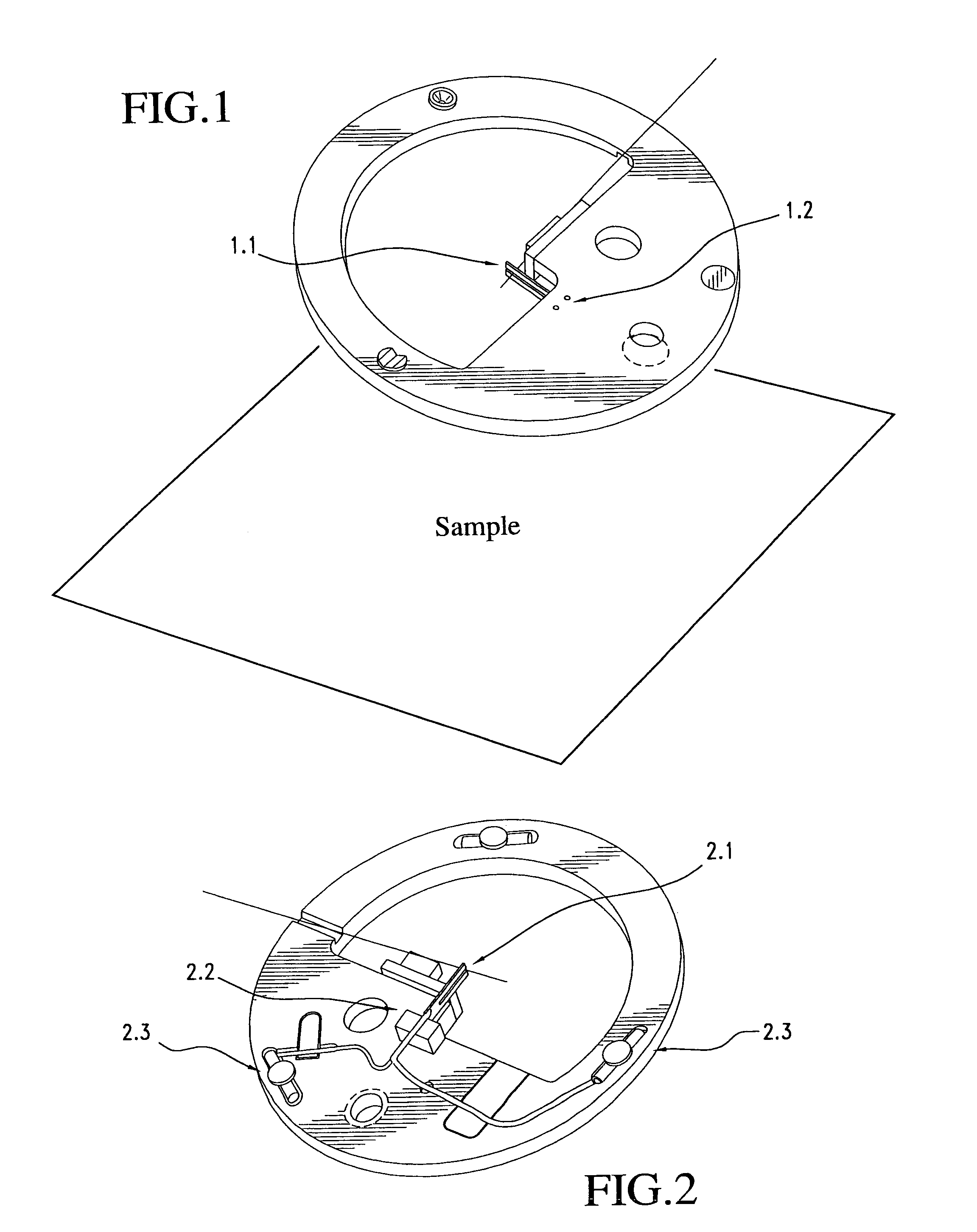
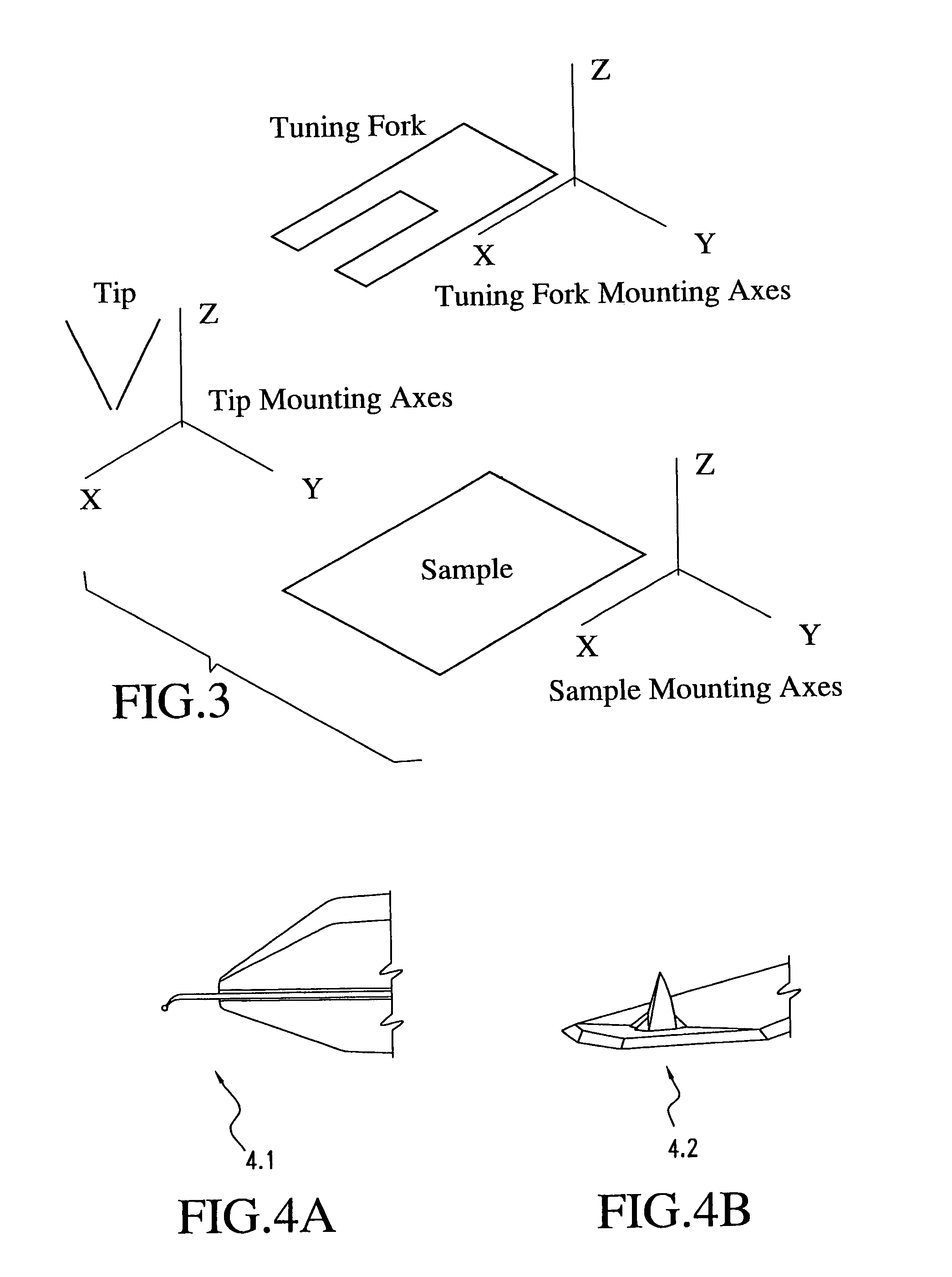
[0047]In one preferred method of the invention, illustrated in FIGS. 1 and 2, a tuning fork (1.1 and 2.1) is mounted on a fork holder (2.2). The mounting of the tuning fork on the fork holder can be in one of several directions. The tuning fork can be used as has been shown in FIGS. 1 and 2, or can be placed, in accordance with the invention, in any relative orientation to the sample. In FIG. 3 the tuning fork is diagrammatically shown with three imposed axes. Sample and tip axes are also indicated. The tuning fork can be placed with the z axis parallel to the sample z axis or any other of the tuning fork axes can be placed parallel to the sample z axis; other orientations are also possible. The oscillation of the tuning fork is along the y axis of the tuning fork

[0048]Also shown in FIG. 3 is a SPM tip relative to its own set of axes. The tip can be associated with either a straight fiber or a cantilevered fiber (4.1), as illustrated in FIG. 4A, or with a sili...


PUM

PropertyMeasurementUnit
optical axisaaaaaaaaaa
scanned probe microscopyaaaaaaaaaa
confocal optical microscopeaaaaaaaaaa

Abstract

The invention is directed to a scanned probe microscope including one plate allowing for tip scanning and the other allowing for sample scanning, with the optical axis of the scanned probe microscope being free to permit incorporation into standard optical microscopes. The top plate can be hinged onto the bottom plate, or the top plate can simply be placed on the bottom plate and a rough approach is caused by a dc motor or other mechanism which will enable the two flat plate scanners to have a large z range. In another embodiment, the microscope includes three plates which allow sample scanning, tip scanning and two tips to be operational at the same time.
A microscope in accordance with the invention may use a liquid cell, may use a near-field optical element made of silicon cantilever technology, or may use an apertureless probe for apertureless near-field scanning optical microscopy.
The microscope may use a tuning fork for feedback in any combination of geometries of tip, sample and tuning fork and with or without gluing of the tip to the tuning fork and with control of tip attachment or near-attachment to the tuning fork. The control of tip attachment to the tuning fork may be based on near zero backlash movement technology, and the tuning fork can be used in non-contact, contact and intermittent contact modes of operation. A fiber based feedback system may use either straight or cantilevered fibers, and the detection of signals may be based on amplitude, phase, wavelength or other optical parameters that can be used to monitor the movement of an SPM sensor.

Description

FIELD OF THE INVENTION[0001]The field of this invention is the design of a unique ultra-thin scanning probe microscope that can readily operate and be flexibly re-configured in various different modes of operation with features that have never been previously available. The invention permits unique capabilities in scanned probe microscopy while allowing for full integration with a far-field optical microscope upright or inverted. It also allows for ready integration into low temperature optical cryostats and for use with various accessories. It also allows a variety of tip scanning schemes to be implemented.BACKGROUND OF THE INVENTION[0002]Scanned probe microscopes (SPM) have passed through many phases of development in the past two decades. A critical juncture in the development of these microscopes was the application of the tube piezoelectric scanner, which had previously been used for many years in the phonograph. This scanner was used first in atomic force microscopes (AFM) [G....

Claims


Application Information

Patent Timeline
Patent Type & Authority Patents(United States)
IPC IPC(8): G01N13/10G12B21/20G12B21/22G01Q10/04G01Q20/00G01Q30/02G01Q30/10G01Q60/38G01Q70/02
CPCB82Y35/00G01Q20/02G01Q30/025G01Q60/38G01Q70/02G01Q30/10
Inventor LEWIS, AARONKOMISSAR, ANATOLYTAHA, HISHAMRATNER, ALEXANDER
Owner NANONICS IMAGING LTD
Why Eureka
Try Eureka