Low sonic boom inlet for supersonic aircraft

a supersonic aircraft and low sonic boom technology, applied in the direction of efficient propulsion technologies, machines/engines, transportation and packaging, etc., to achieve the effect of reducing the probability of inlet unstart, high performance, and large operability margins

Inactive Publication Date: 2006-05-23
TECHLAND RES
View PDF10 Cites 78 Cited by
  • Summary
  • Abstract
  • Description
  • Claims
  • Application Information

AI Technical Summary

Benefits of technology

[0008]The inlets disclosed and claimed herein provide high performance, large operability margins, i.e. terminal shock stability that reduces the probability of inlet unstart, and contribute little or nothing to the overall sonic boom signature of the aircraft. The characteristics of these inlets include very high internal area contraction or compression and very low external surface angles. The design concept of this invention is a very high to all internal compression inlet, in which all shocks from the internal inlet surfaces are captured and reflected inside the inlet duct (no compression system shocks radiated external to the inlet duct). Additionally, they allow all of the external nacelle surfaces to be completely or very nearly aligned with the external flow (zero external surface angles). These low profile external surfaces do not produce a shock wave that contributes to the sonic boom problem. In this invention, an all-internal compression inlet is combined with a shock stability bleed system. The innovative application of a shock stability bleed system can prevent inlet unstarts caused by both internal and external flow disturbances, and provide large shock stability margins, thereby making the all internal-compression, or near all-internal compression inlets feasible for application to supersonic cruise vehicles.
[0009]The inlet shock stability system consists of bleed regions that duct bleed airflows to variable area exits. The stability system incorporates either passive or active exit area controls. This system prevents inlet unstarts by removing airflow through a large open throat bleed region to compensate for reductions in diffuser (engine) corrected airflow demand. Because the stability bleed is not removed until the inlet terminal shock moves upstream over the bleed region, the necessary normal shock operability margin is provided without compromising inlet performance (total pressure recovery, and distortion) and without requiring prohibitive amounts of performance bleed during normal inlet operation. Research has demonstrated that the utilization of a variable bleed exit on a large open throat bleed region can provide very large inlet stability margins for both internal and external airflow variations. The appropriate placement of a stability bleed system in the throat of an all internal-compression inlet makes the design of such a configuration feasible.

Problems solved by technology

These low profile external surfaces do not produce a shock wave that contributes to the sonic boom problem.

Method used


Image

  • Low sonic boom inlet for supersonic aircraft
  • Low sonic boom inlet for supersonic aircraft
  • Low sonic boom inlet for supersonic aircraft

Examples


Embodiment Construction

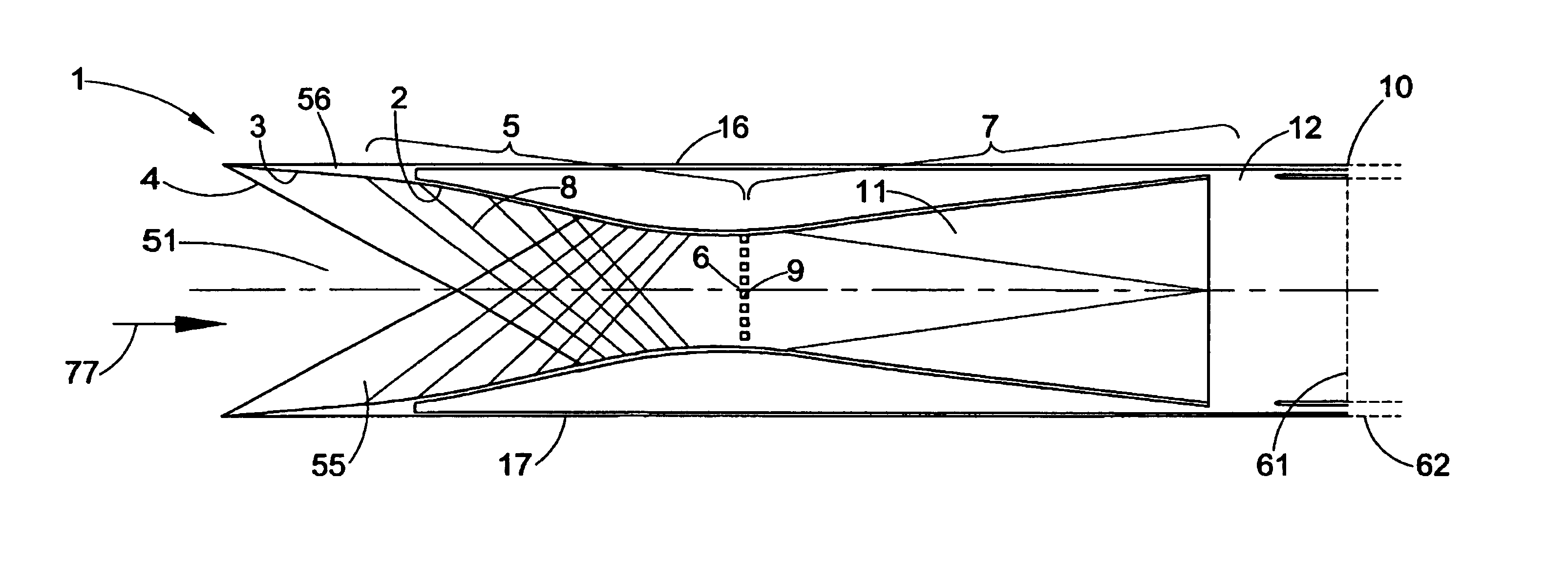
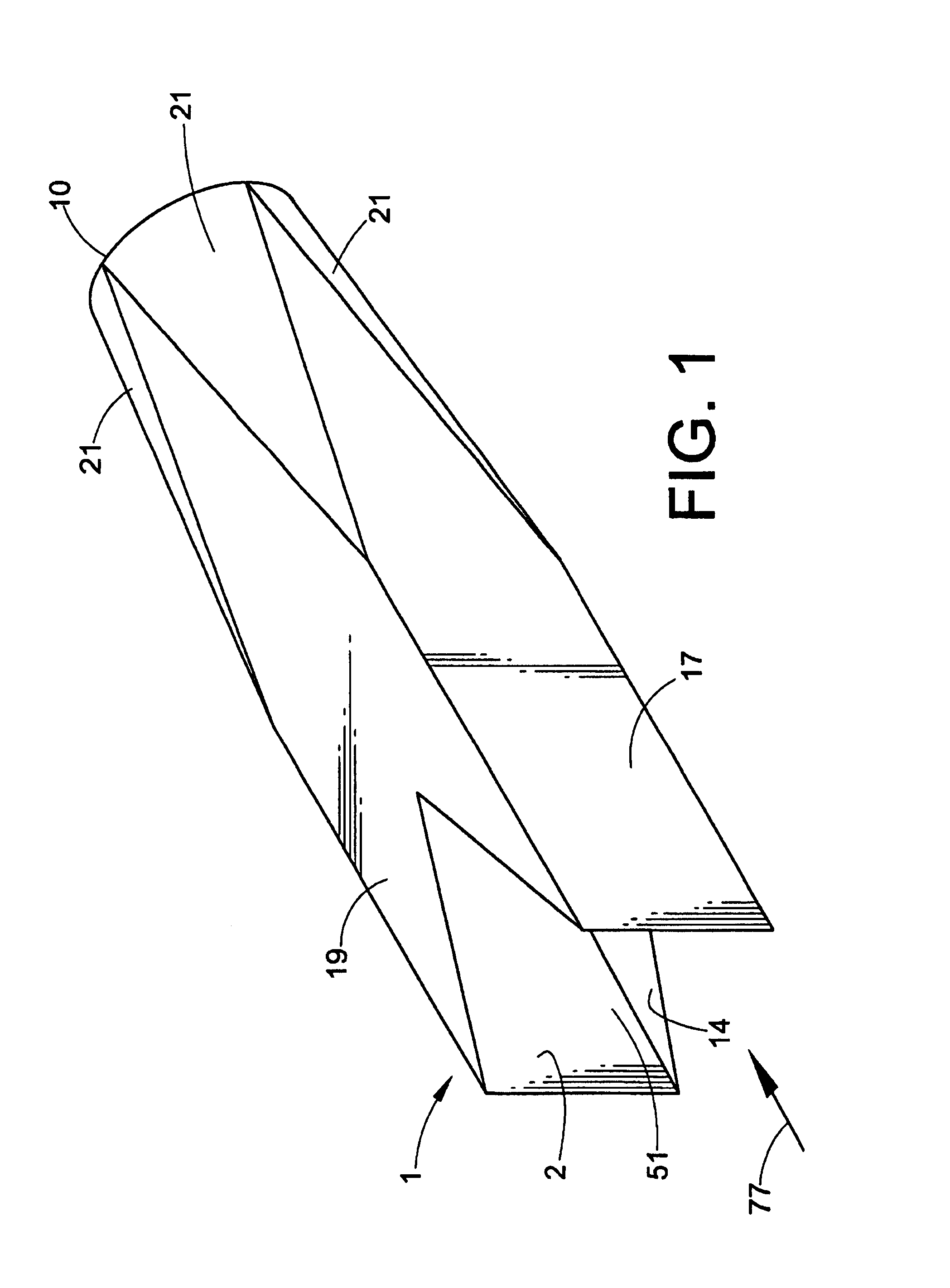
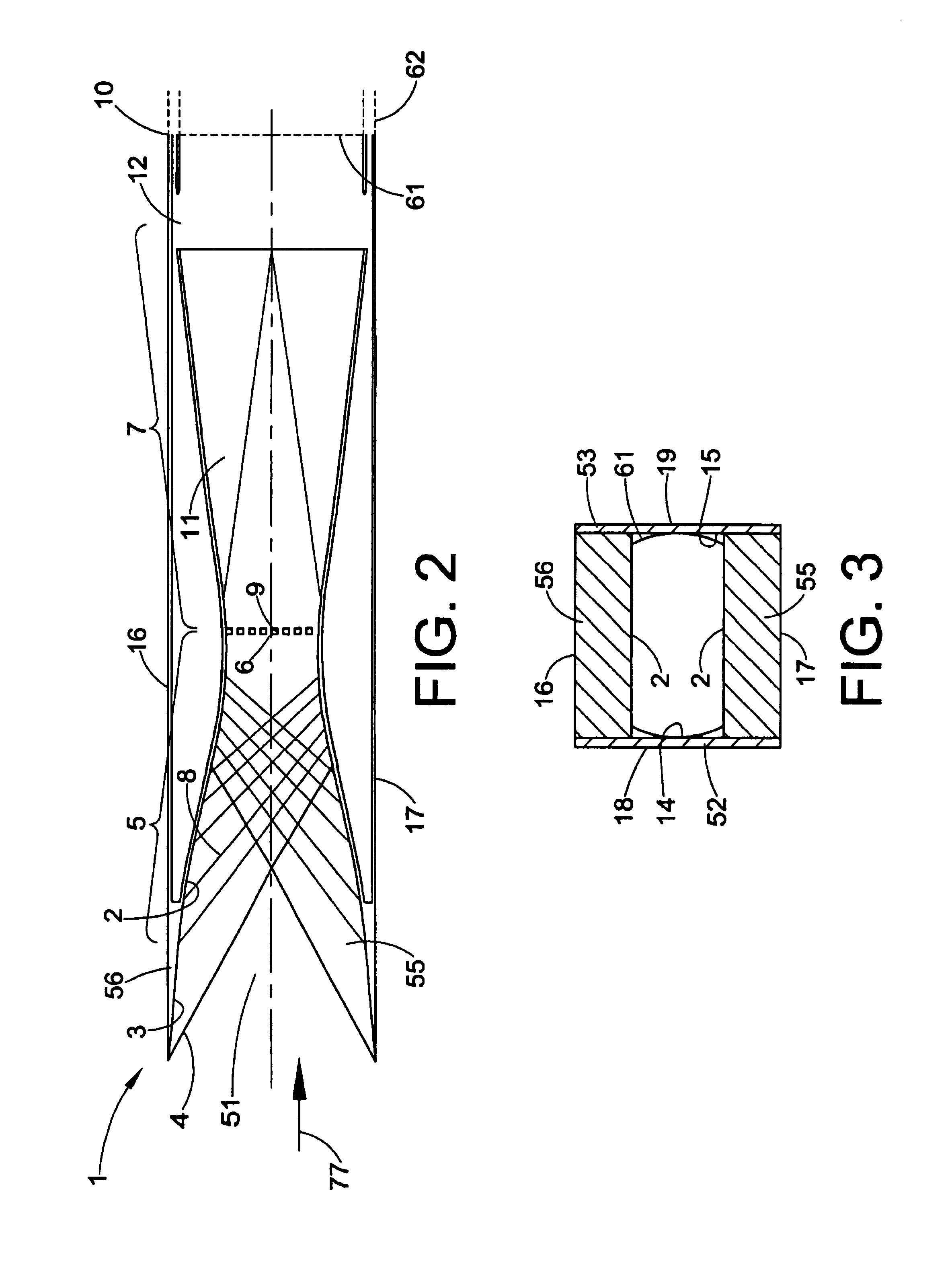
[0024]The basic inlet concept is presented in FIGS. 1 through 14. FIG. 1 shows an isometric view of the inlet, referred to generally as 1, and FIGS. 2 through 4 present cross-sections of the configuration. The isometric sketch in FIG. 1 depicts a supersonic inlet 1 in which all the external surfaces are flow-aligned, i.e aligned with the airflow approaching the inlet. The airflow approaching the inlet is substantially parallel to the inlet centerline; therefore, surfaces that are flow-aligned with the freestream airflow are also parallel to the inlet centerline. The initial external cross-sectional shape of the inlet is rectangular and then transitions as indicated by the surfaces 21 to a round nacelle at the downstream end 10. If the propulsion system uses a square or rectangular nozzle, transitioning of the inlet surfaces, as shown by surface 21 in FIG. 1, to a round nacelle is not required; therefore, the rectangular cross-section would be continued to the end of the nacelle, sta...


PUM


Abstract

All-internal compression inlets for supersonic aircraft, with variable geometry systems and shock stability bleed systems provide high performance, large operability margins, i.e. terminal shock stability that reduces the probability of inlet unstart, and contribute little or nothing to the overall sonic boom signature of the aircraft. These inlets have very high internal area contraction or compression and very low external surface angles. All shocks from the internal inlet surfaces are captured and reflected inside the inlet duct, and all of the external nacelle surfaces are substantially aligned with the external airflow. The inlet shock stability system consists of bleed regions that duct bleed airflows to variable area exits with passive or active exit area controls. This reduces the risk of inlet unstarts by removing airflow through a large open throat bleed region to compensate for reductions in diffuser (engine) corrected airflow demand. Because the stability bleed is not removed until the inlet terminal shock moves upstream over the bleed region, the necessary normal shock operability margin is provided without compromising inlet performance (total pressure recovery, and distortion).

Description

CROSS REFERENCE TO RELATED APPLICATIONS[0001]This application claims the benefit of U.S. provisional application Ser. No. 60 / 235,359 filed on Sep. 26, 2000.FIELD OF THE INVENTION[0002]This invention relates to air intakes for flight vehicles and, more particularly, to air intakes for aircraft that are designed to fly at supersonic speeds.BACKGROUND OF THE INVENTION[0003]Inlets for propulsion systems for high speed supersonic aircraft are designed to efficiently decelerate the approaching high-speed airflow to velocities that are compatible with efficient airbreathing engine operation and to provide optimum matching of inlet airflow supply to engine airflow requirements. Entrance airflow velocities to existing air-breathing engines must be subsonic; therefore, it is necessary to decelerate the airflow speed during supersonic flight. The airflow velocities are slowed from supersonic speeds (above the speed of sound) to engine entrance Mach numbers that are subsonic (below the speed of...

Claims


Application Information

Patent Timeline
Patent Type & Authority Patents(United States)
IPC IPC(8): B64B1/24F02C7/042
CPCF02C7/042B64D2033/026Y02T50/671Y02T50/60Y10T137/0536
Inventor SANDERS, BOBBY W.WEIR, LOIS J.
Owner TECHLAND RES
Why Eureka
Try Eureka