Flexible tip medical instrument

a flexible tip and medical instrument technology, applied in medical science, surgery, vaccination/ovulation diagnostics, etc., can solve the problems of no longer acceptable practice, no effect of obtaining adequate liver tissue, and generalized pain

Inactive Publication Date: 2006-05-23
PROMEX TECH
View PDF12 Cites 107 Cited by
  • Summary
  • Abstract
  • Description
  • Claims
  • Application Information

AI Technical Summary

Benefits of technology

[0018]One object of the invention is to provide biopsy devices and assemblies specifically designed for accessing and performing a biopsy on an internal organ situated deep within a body. One advantage of the present invention is that it can be achieved through inexpensive modifications of existing devices. Yet another advantage of the present invention is its capability to yield a sufficient amount of biopsy samples using a single device. Yet another advantage is that the present invention does not require complicated cabling or the attachment or welding of similar or dissimilar materials to comprise the flexible portions. These and other objects, advantages and features are accomplished according to the devices, assemblies and methods of the present invention.

Problems solved by technology

This method, although effective in obtaining an adequate amount of tissue from the liver, is no longer acceptable practice, since it is not uncommon for the patient to suffer from serious health complications caused by the biopsy.
For example, patients generally experience extreme pain, and additionally, the liver profusely bleeds after percutaneous biopsy.
Moreover, liver biopsies are typically performed on patients having liver disease, liver transplants and coagulation disorders, and such conditions further complicate percutaneous liver biopsies.
A problem associated with this type of biopsy device is that the rigid inner and outer needles 26, 22 are metallic, commonly stainless steel, and lack the flexibility to freely move within the introducer 34 due to the significant curve 42 located at the introducer's distal end 44 (FIG. 4).
Movement of the introducer once it is ideally placed is undesirable since damage to the surrounding tissue and poor biopsy samples are frequently the result of such movement.
Moreover, repeatedly firing the biopsy device 20 during subsequent sampling events causes the sliding surfaces of the outer needle 22 and inner wall 46 of introducer 34 to become “galled” i.e., deformation of the sliding surfaces, resulting in an additional and significant decrease in performance of the firing mechanism 27.
As a result, little if any tissue is recovered and the device 20 may be permanently damaged before an adequate specimen is captured.
This is unfortunately common and leads to a significant and unwarranted cost increase due to equipment, personnel and room charges, as well as an extended biopsy procedure for the patient.
Unfortunately, the needles tend to bind with the lumen walls of the long introducer at the bend.
Problematically, the flexible cable and cannula assembly are generally flaccid in disposition providing a biopsy tip, located at the distal end of the cable and cannula assembly, that is unwieldily and uncontrollable.
Moreover, a significant amount of energy of the firing device is lost by the flexible cannula and wire assembly as it yields when the firing device is activated.
These circumferential slots provide a limited measure of binding relief at the bend, however an unsatisfactory level of relief for deep internal organ biopsy.
In addition, these slots result in a loss of axial strength, and ultimately, a loss in precision between the stationary tube and the inner movable tube.
As an added disadvantage, it is very expensive to produce the accordion-like design of these slots.
Although the device is flexible, it is a motorized surgical cutting device, and the degree of complexity introduced by the concept is not desirable in the single and double action biopsy devices used for intravascular accessed biopsy procedures.

Method used


Image

  • Flexible tip medical instrument
  • Flexible tip medical instrument
  • Flexible tip medical instrument

Examples


Embodiment Construction

[0041]For the purposes of promoting an understanding of the principles of the invention, reference will now be made to the embodiments illustrated in the drawings and specific language will be used to describe the same. It will nevertheless be understood that no limitation of the scope of the invention is thereby intended. The invention includes any alterations and further modifications in the illustrated devices and described methods and further applications of the principles of the invention that would normally occur to one skilled in the art to which the invention relates.

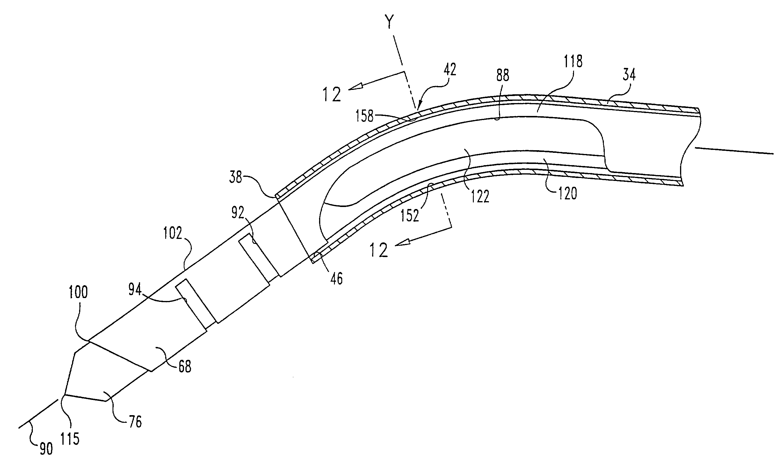
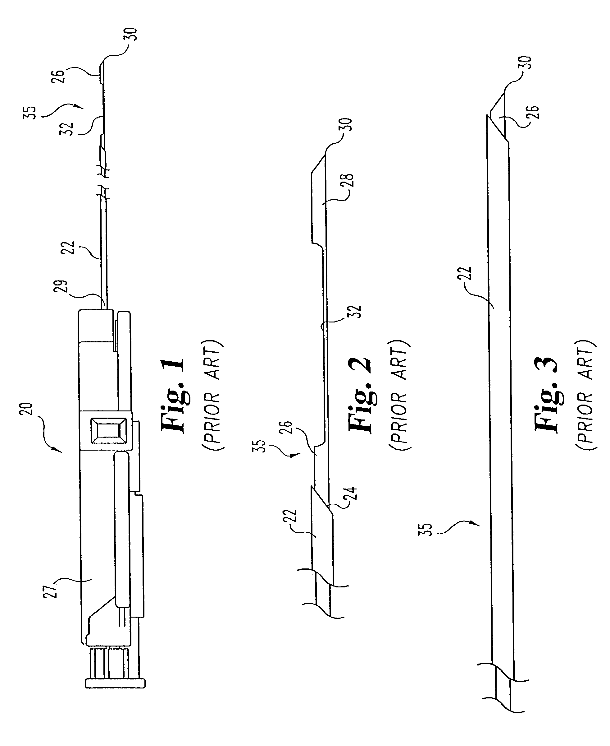
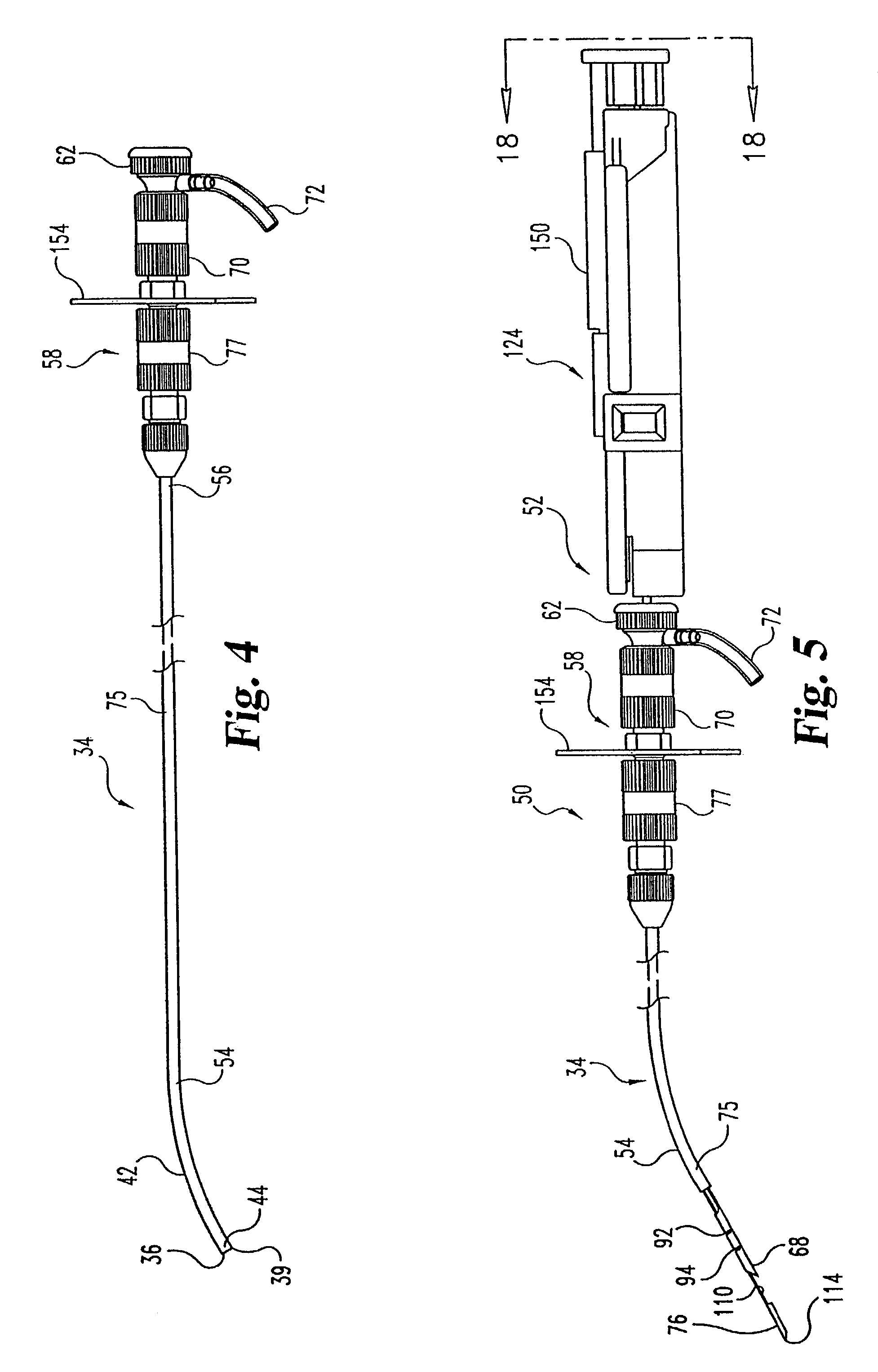
[0042]The present invention provides devices and assemblies to access an internal organ through a patient's venous and arterial system to obtain a tissue specimen from the target organ. A long narrow tube or introducer cannula is precisely placed through interconnecting veins and arteries along a tortuous path. Previously used coring needle assemblies exhibited pronounced binding with the introducer cannula as t...


PUM


Abstract

A needle set includes a hollow outer needle and an inner needle slidably disposed within the lumen of the outer needle. The outer needle defines a first relief notch having a length that is longer than its width. The inner needle defines a second relief notch, which is also longer than wide. The needle set has a first position with the first relief notch superposed over the second relief notch. A slot may also be defined in the outer needle. A firing mechanism may be engaged to the proximal ends of the needles to move the needles relative to one another. The needle set may be used with an elongated introducer cannula having a curved portion with the outer and inner needles being sufficiently flexible to traverse the curved portion without binding between the needles.

Description

[0001]This application is a continuation of International Application PCT / US01 / 44388 filed Nov. 28, 2001, which is a continuation of application Ser. No. 09 / 723,845, filed on Nov. 28, 2000, now U.S. Pat. No. 6,419,641.FIELD OF THE INVENTION[0002]The present invention relates generally to biopsy systems. Specifically, the invention concerns devices for obtaining biopsy samples through veins and arteries.BACKGROUND OF THE INVENTION[0003]In the practice of diagnostic medicine, it is often necessary or desirable to perform a biopsy, or to sample selected tissue from a living patient for medical evaluation. Cytological and histological studies of the biopsy sample can then be performed as an aid to the diagnosis and treatment of disease. Biopsies can be useful in diagnosing and treating various forms of cancer, as well as other diseases in which a localized area of affected tissue can be identified.[0004]During the biopsy procedure, care is taken to minimize the physical trauma inflicted...

Claims


Application Information

Patent Timeline
Patent Type & Authority Patents(United States)
IPC IPC(8): A61B10/00A61B10/02A61B10/04
CPCA61B10/0275A61B2010/045A61B2010/0208
Inventor MARK, JOSEPH L.MILLER, MICHAEL E.
Owner PROMEX TECH
Why Eureka
Try Eureka