Methods for delivering tissue implant material with a high pressure applicator

a tissue implant and applicator technology, applied in the field of high-pressure applicators for tissue implant material delivery, can solve problems such as material drainage out, and achieve the effects of preventing contamination of the applicator, finer pitch, and increasing the margin of error

Inactive Publication Date: 2006-05-23
NEUROTHERM
View PDF80 Cites 168 Cited by
  • Summary
  • Abstract
  • Description
  • Claims
  • Application Information

AI Technical Summary

Benefits of technology

[0019]To help account for the possibility of excess implant material and associated potential of fouling of the applicator by such excess, a larger size of the introduction section than strictly required for the venting feature discussed above may be used to act as a catch basin for implant material. This will provide an increased margin of error in pouring implant material into the applicator before overflowing the introduction section. Further, the walls of such an enlarged catch basin may help to prevent contamination of the applicator by virtue of adherence of the implant material to the surface area provided during inversion or agitation of the applicator.
[0020]The present invention may include a funnel or increased-size target region integrated into the first column, adjacent to the introduction section, to aid in pouring implant material into the applicator. Drive threads may be placed on the exterior of the funnel section. However, when no integral funnel is provided, drive threads may be placed exterior to the introduction section which may be of a finer pitch or higher thread count than those on a larger diameter. A smaller diameter and / or finer threads will provide for greater mechanical advantage for generating higher driving pressures more easily. To help in loading material into the applicator when no integral funnel is used, a separate funnel element may be provided to interface with the introduction section.

Problems solved by technology

Introduction of a larger amount of implant material is not only wasteful, but may result in material drainage out of the introduction section into other parts of the applicator—especially when the applicator is inverted or turned as will often be the case in preparing PMMA implant material for delivery.

Method used


Image

  • Methods for delivering tissue implant material with a high pressure applicator
  • Methods for delivering tissue implant material with a high pressure applicator
  • Methods for delivering tissue implant material with a high pressure applicator

Examples


Embodiment Construction

[0031]An example procedure for using precision instruments according to the present invention in an intravertebral vertebroplasty will now be described. It is expressly noted, however, that this invention is useable in a myriad of other procedures where virtually any flowable material to be delivered to a patient under pressure is employed. But for percutaneous vertebroplasty, initially a surgeon identifies a landmark with the aid of fluoroscopy or other imaging technique. Next, an injection is given to anesthetize the skin where insertion will occur. A long needle, having a length sufficient to percutaneously access the periosteum of the target vertebra is then used to inject anesthesia subperiostially.

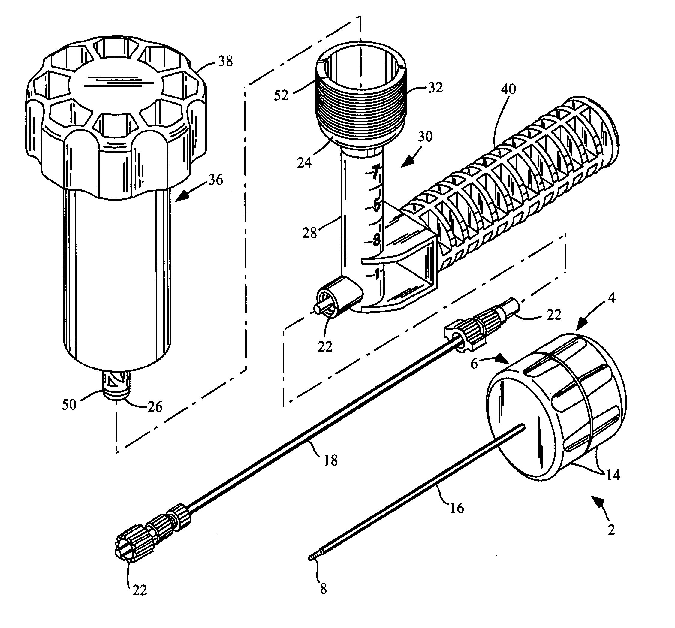
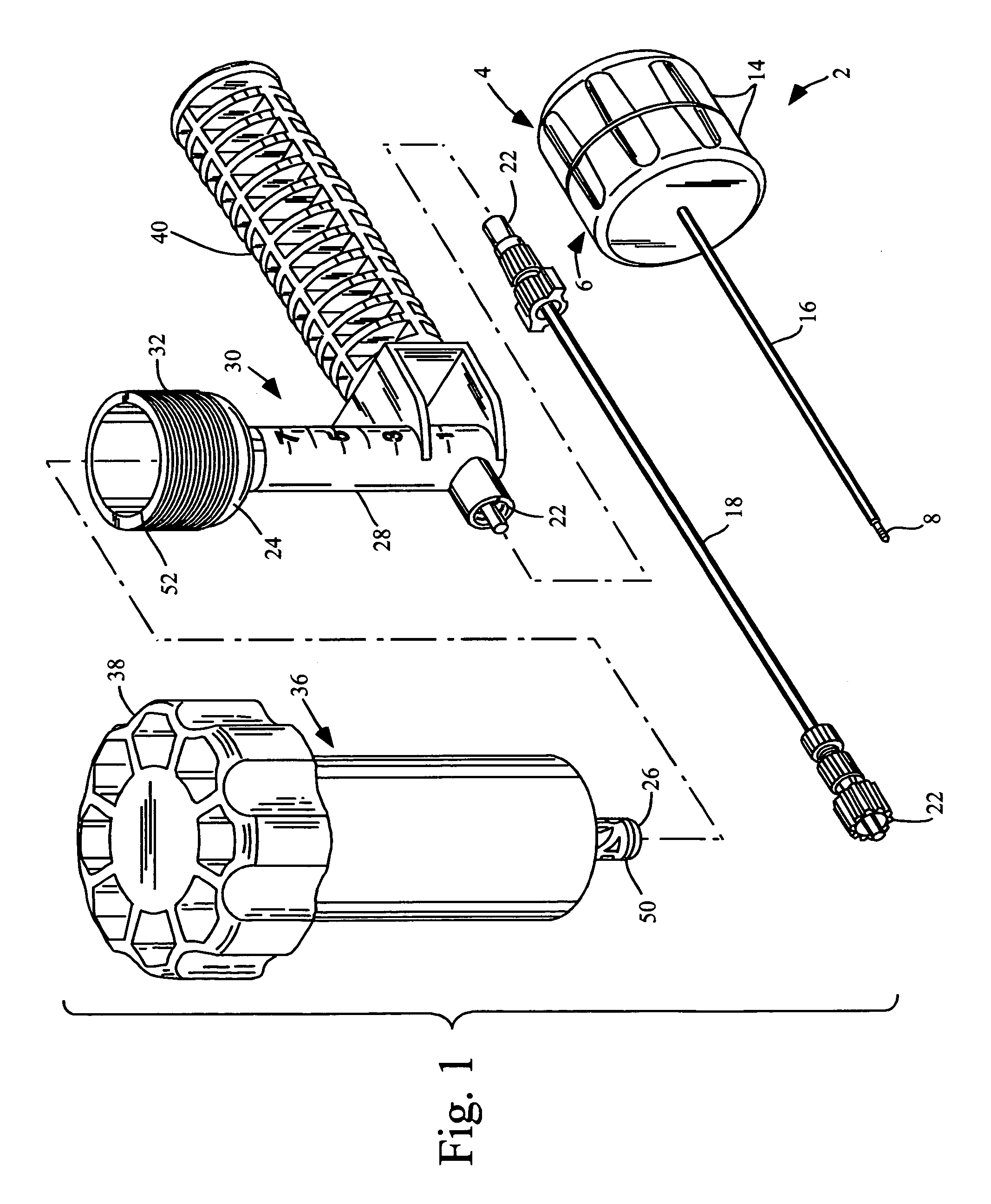
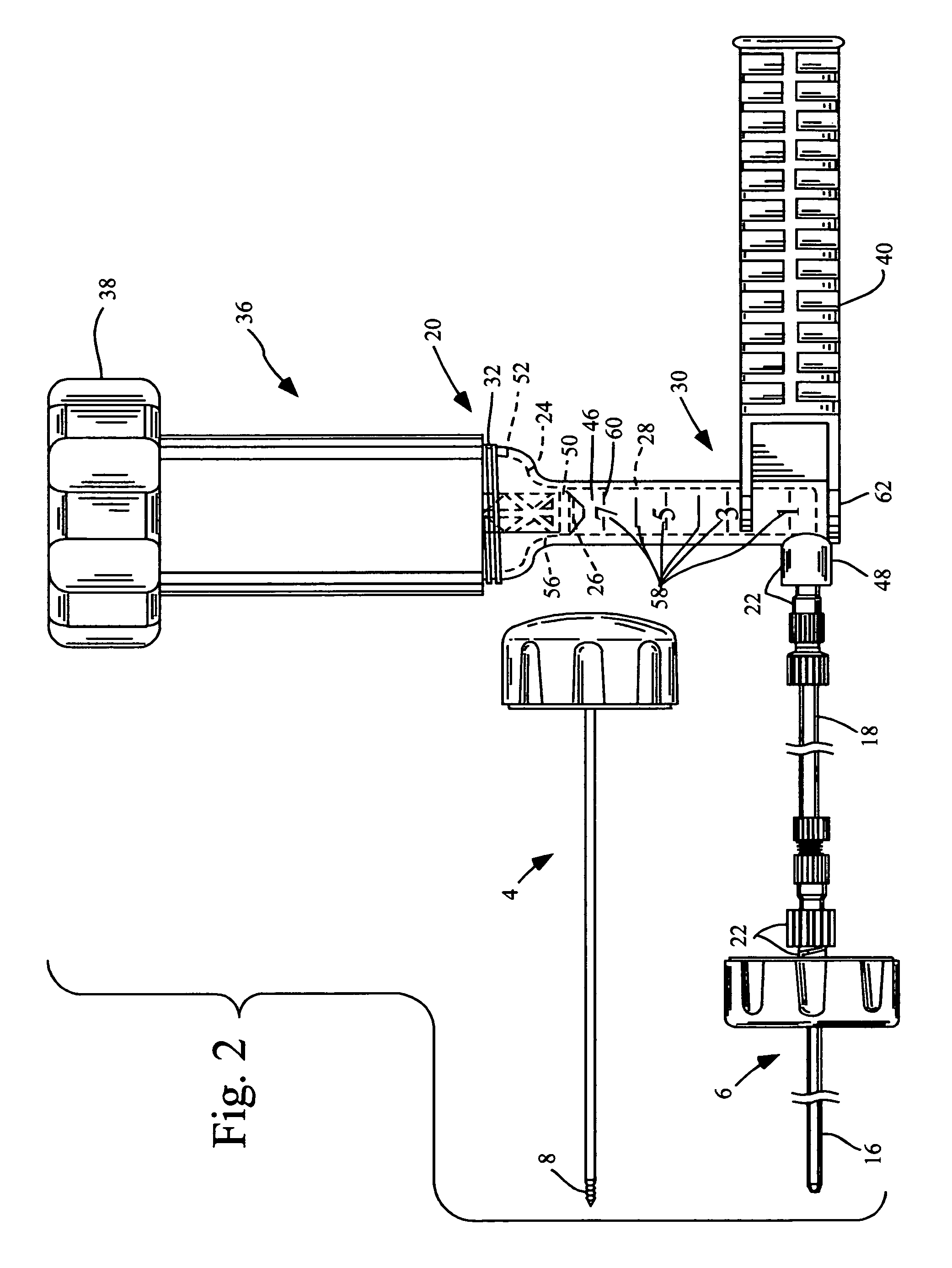
[0032]After sufficient time has passed to effectively anesthetize the skin, an incision is made through the skin with a scalpel. A combined stylet and cannula 2 (such as stylet 4 and cannula 6 threaded together, as shown in FIG. 1) and further described in U.S. patent Ser. No. 09 / 409...


PUM


Abstract

This relates to an improved delivery system for accurately loading and controlling the delivery of flowable material to a patient. Particularly, the system may be used in the injection of hard tissue implant materials such as PMMA under pressures up to about 4000 psi. The system includes an applicator with a first column having an implant material introduction section adapted to provide for effective loading of the implant material and a second column housing a piston. The introduction section has a larger size than that of a vessel section or bore in which the requisite pressure seal between the piston and bore wall is formed. The first column may include an introduction section flared open to an included larger funnel-like opening or a separate funnel may be used that interfaces with the introduction section to facilitate the introduction of implant material. Handles on the first and second columns to be turned relative to each other to advance the columns toward each other may be provided for manual actuation of the applicator to drive implant material through a cannula and deliver implant material to a desired site.

Description

CROSS REFERENCE TO RELATED APPLICATION[0001]This is a divisional of application Ser. No. 09 / 408,690, filed Sep. 30, 1999, entitled “High Pressure Delivery System” now U.S. Pat. No. 6,783,515.TECHNICAL FIELD[0002]The present invention relates to a system for more accurately controlling the delivery of flowable material to a patient. Particularly, the system may be used in the injection of hard tissue implant materials. Features of the invention provide for effective loading of an applicator configured to generate high fluid delivery pressures.BACKGROUND OF THE INVENTION[0003]The introduction of flowable material to an implantation site within a patient to effect one or more therapeutic goals is well known. The flowable material itself may be of high or low viscosity. Matter ranging from typical fluids or solutions to non-Newtonian fluids, pastes, gels and the like has been used for one purpose or another in the medical arts.[0004]It is well-recognized that syringes may be used for pe...

Claims


Application Information

Patent Timeline
Patent Type & Authority Patents(United States)
IPC IPC(8): A61B17/60A61B17/88A61F2/46
CPCA61B17/8822
Inventor MILLER, SCOTT H.PREISSMAN, HOWARD
Owner NEUROTHERM
Why Eureka
Try Eureka