Apparatus and process for power recovery

a technology of power recovery and apparatus, applied in the field of apparatus and process for power recovery, arrangement for recovering power, can solve the problems of imposing a great deal of force loading and rotational moment on the expander turbine inlet line, rapid heat up of hot wall piping, etc., and achieves the effect of avoiding mechanical damage to the power recovery expander and minimizing the thermal expansion thereo

Active Publication Date: 2006-05-23
UOP LLC
View PDF9 Cites 47 Cited by
  • Summary
  • Abstract
  • Description
  • Claims
  • Application Information

AI Technical Summary

Benefits of technology

[0014]If the actual flowing volume of the clean gas in the main clean gas conduit exceeds a level at which the power recovery unit is rated, a valve in the bypass clean gas conduit is opened to a proportional degree, so a portion of the clean gas being directed to the power recovery unit can be re-directed to bypass the power recovery unit, and maintain proper pressure control of the FCC regenerator and avoid mechanical damage to the power recovery expander. The bypass clean gas conduit is anchored on the TSS vessel instead of on the main clean gas conduit to the power recovery unit, so sudden exposure of the bypass clean gas conduit to hot gases and its concomitant rapid thermal expansion will not suddenly impose a load or moment on the power recovery unit beyond allowance. Hence, equipment, engineering, and installation labor necessary for neutralizing such effects are not necessary. Moreover, because the bypass clean gas conduit does not join with a conduit to the power recovery unit, the bypass clean gas conduit may be lined with insulating refractory to minimize thermal expansion thereof without fear that spalling refractory will damage the power recovery unit.

Problems solved by technology

However, as the bypass valve opens, the flow of hot flue gas would cause the hot wall piping to rapidly heat up and thermally expand.
The resultant pipe expansion would impose a great deal of force loading and rotational moment on the expander turbine inlet line.

Method used


Image

  • Apparatus and process for power recovery
  • Apparatus and process for power recovery
  • Apparatus and process for power recovery

Examples


Embodiment Construction

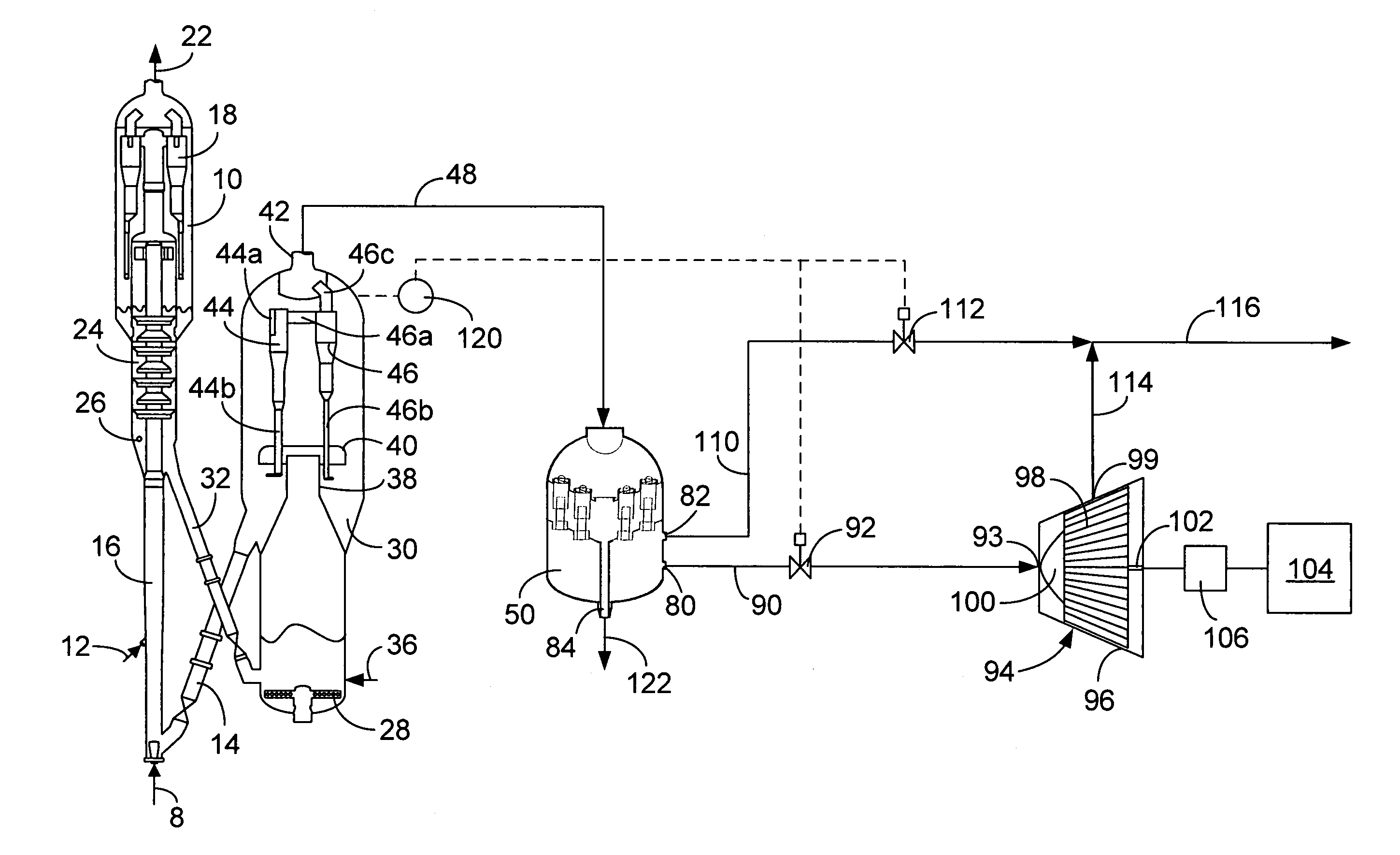
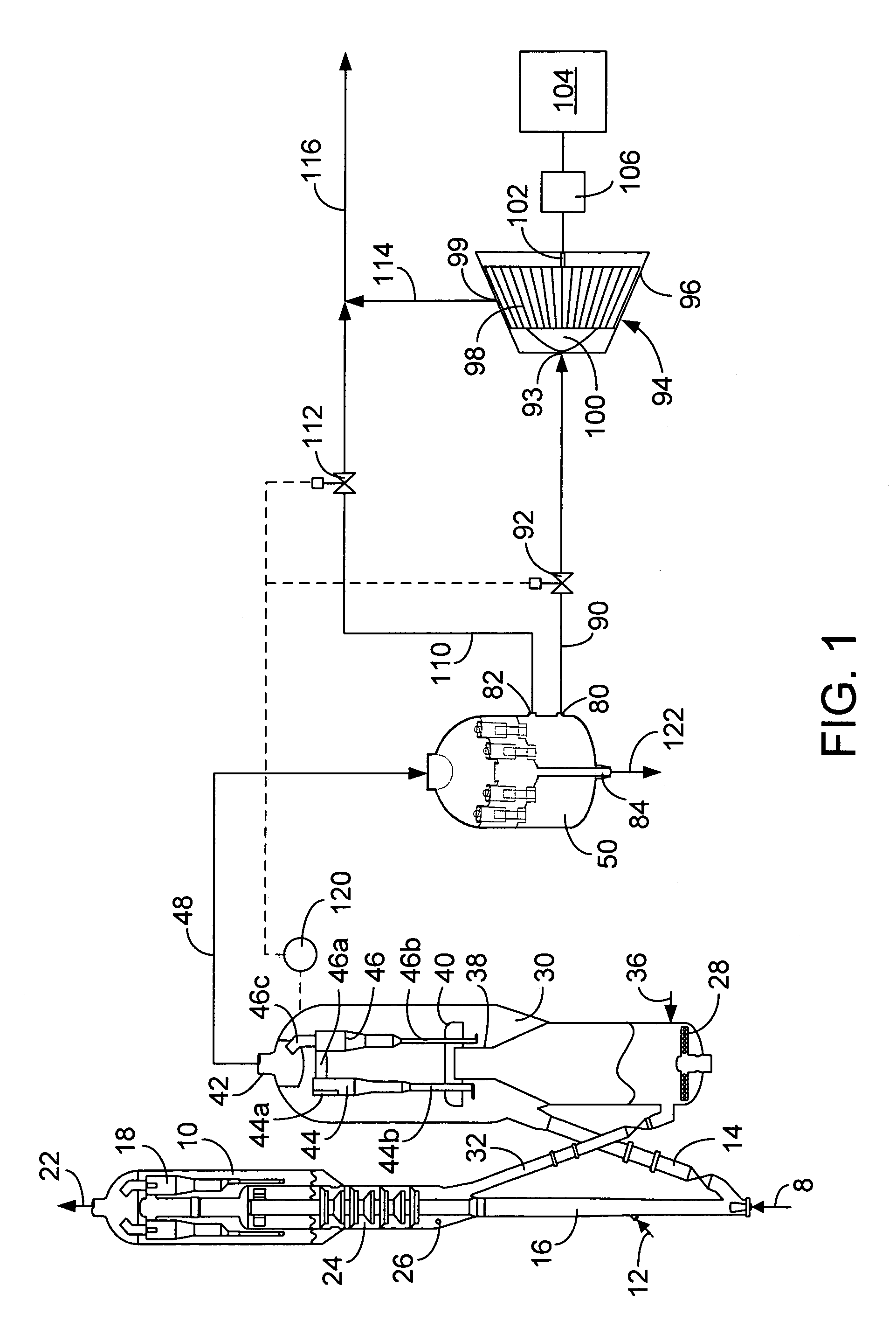
[0019]The present invention applies to the purification of a broad range of solid-contaminated gas streams, and especially those containing dust particles in the 1 to 20 μm range. A number of commercial gas purification operations meet this description, including the treatment of effluent streams of solid catalyst fluidized bed processes, coal fired heaters, and power plants. Several well-known refinery operations rely on fluidized bed technology, such as a preferred embodiment of the process for converting methanol to light olefins, as described in U.S. Pat. No. 6,137,022, using a solid catalyst composition. Another area of particular interest lies in the purification of FCC effluent streams that contain entrained catalyst particles resulting from attrition, erosion, and / or abrasion under process conditions within the reactor.

[0020]As mentioned, fluid catalytic cracking (FCC) is a well-known oil refinery operation relied upon in most cases for gasoline production. Process variables...


PUM

PropertyMeasurementUnit
temperaturesaaaaaaaaaa
pressureaaaaaaaaaa
pressureaaaaaaaaaa

Abstract

Disclosed is a third stage separator which includes two main clean gas outlets. One main clean gas outlet communicates with a power recovery unit such as an expander turbine while the second main clean gas outlet communicates with a conduit that bypasses the expander turbine. The present invention avoids use of the extra equipment, engineering and installation labor required to prevent the bypass conduit from placing a force load on the line to the power recovery unit.

Description

FIELD OF THE INVENTION[0001]The present invention relates to a novel arrangement for recovering power from a gas stream laden with solids. Specifically, the present invention relates to a third stage separator (TSS) vessel for removing catalyst fines from hot regenerator flue gas of a fluid catalytic cracking (FCC) unit followed by a power recovery unit.BACKGROUND OF THE INVENTION[0002]FCC technology, now more than 50 years old, has undergone continuous improvement and remains the predominant source of gasoline production in many refineries. This gasoline, as well as lighter products, is formed as the result of cracking heavier (i.e. higher molecular weight), less valuable hydrocarbon feed stocks such as gas oil. Although FCC is a large and complex process involving many factors, a general outline of the technology is presented here in the context of its relation to the present invention.[0003]In its most general form, the FCC process comprises a reactor that is closely coupled with...

Claims


Application Information

Patent Timeline
Patent Type & Authority Patents(United States)
IPC IPC(8): B01D45/12F02C7/00
CPCB01D45/16B01D45/14
Inventor COUCH, KEITH A.BELL, LEONARD E.JOHNSON, II, RICHARD A.
Owner UOP LLC
Why Eureka
Try Eureka