Fuel cell system and its startup control

a fuel cell and system technology, applied in the field of fuel cell systems, can solve the problems of reducing the usability of the fuel cell vehicle, reducing lengthening the warm-up time so as to reduce the efficiency of the fuel cell, and prolong the warm-up time

Active Publication Date: 2006-05-23
NISSAN MOTOR CO LTD
View PDF9 Cites 6 Cited by
  • Summary
  • Abstract
  • Description
  • Claims
  • Application Information

AI Technical Summary

Benefits of technology

[0008]When starting the fuel cell system at low temperature, the water generated inside the fuel cell and the moisture in the fuel and air condense inside the fuel cell, and may block the fuel and air passage, which is called “water clogging.” Water clogging reduces the efficiency of th

Problems solved by technology

When starting the fuel cell system at low temperature, the water generated inside the fuel cell and the moisture in the fuel and air condense inside the fuel cell, and may block the fuel and air passage, which is called “water clogging.” Water clogging reduces the efficiency of the fuel cell, and in particular, water clogging which occurs during startup lengthens the warm-up time of the fuel cell.
As the frequency of startup operations is high in vehicles, the lengthening of the warm-up time of the fuel cell system reduces the usabil

Method used


Image

  • Fuel cell system and its startup control
  • Fuel cell system and its startup control
  • Fuel cell system and its startup control

Examples


second embodiment

[0040]Next, this invention will be described.

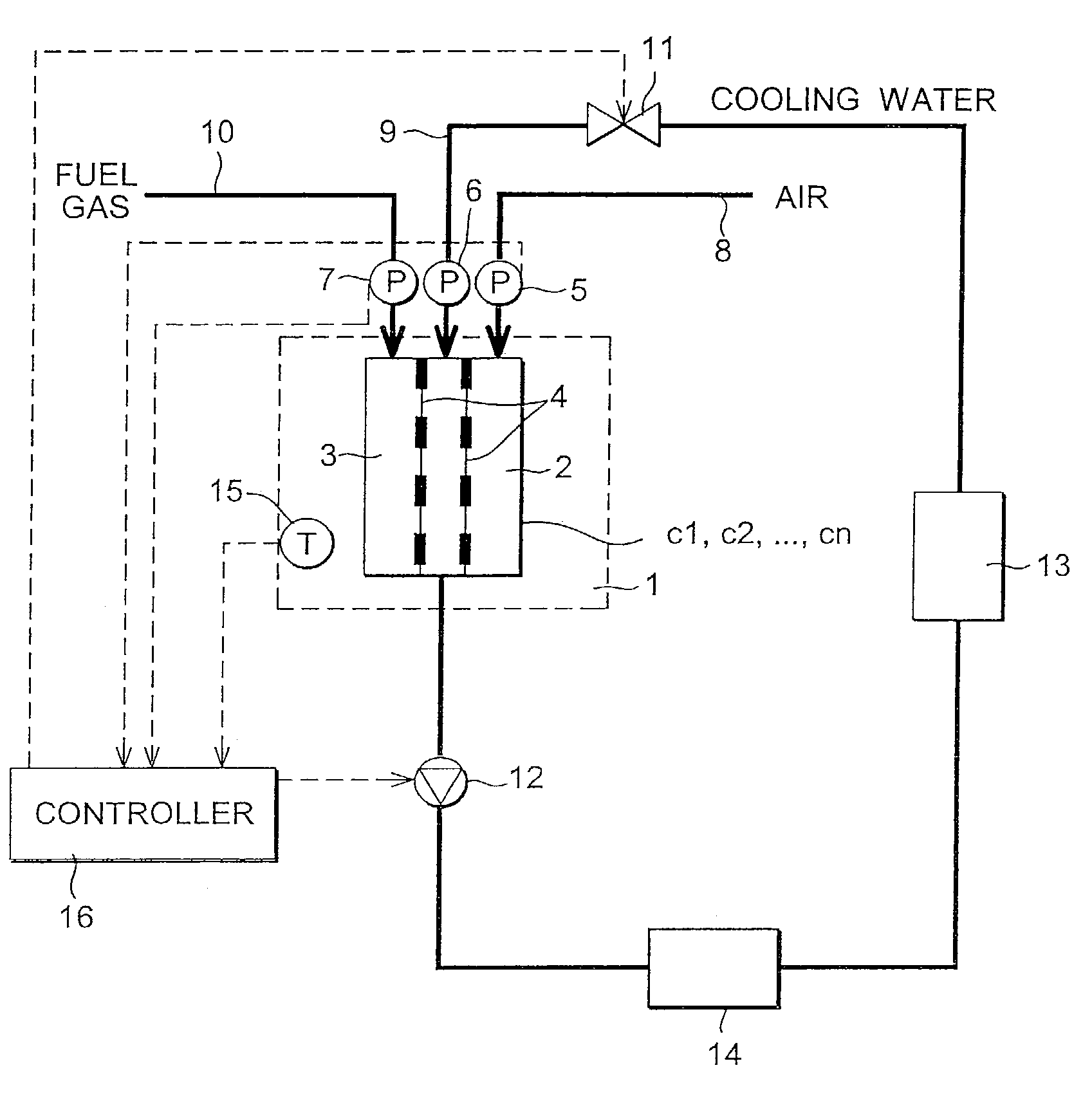
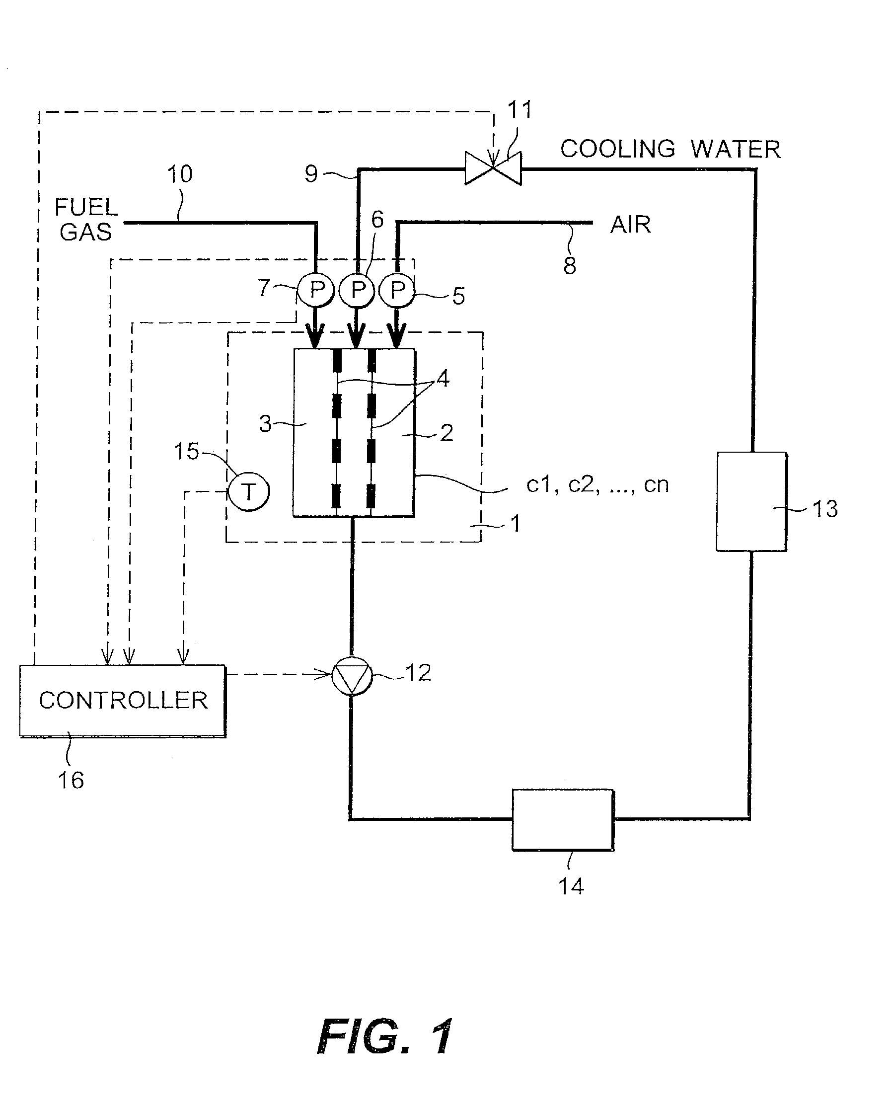
[0041]FIG. 4 shows the construction of a fuel cell system of the second embodiment. Temperature sensors 21 are installed which measure the temperatures in each cell c1, c2, . . . , cn of the fuel cell stack 1, which is a difference from the first embodiment. For convenience, only three sensors 21 have been shown in FIG. 3, but there may be a larger or smaller number of the sensors 21 according to the number of the cells.

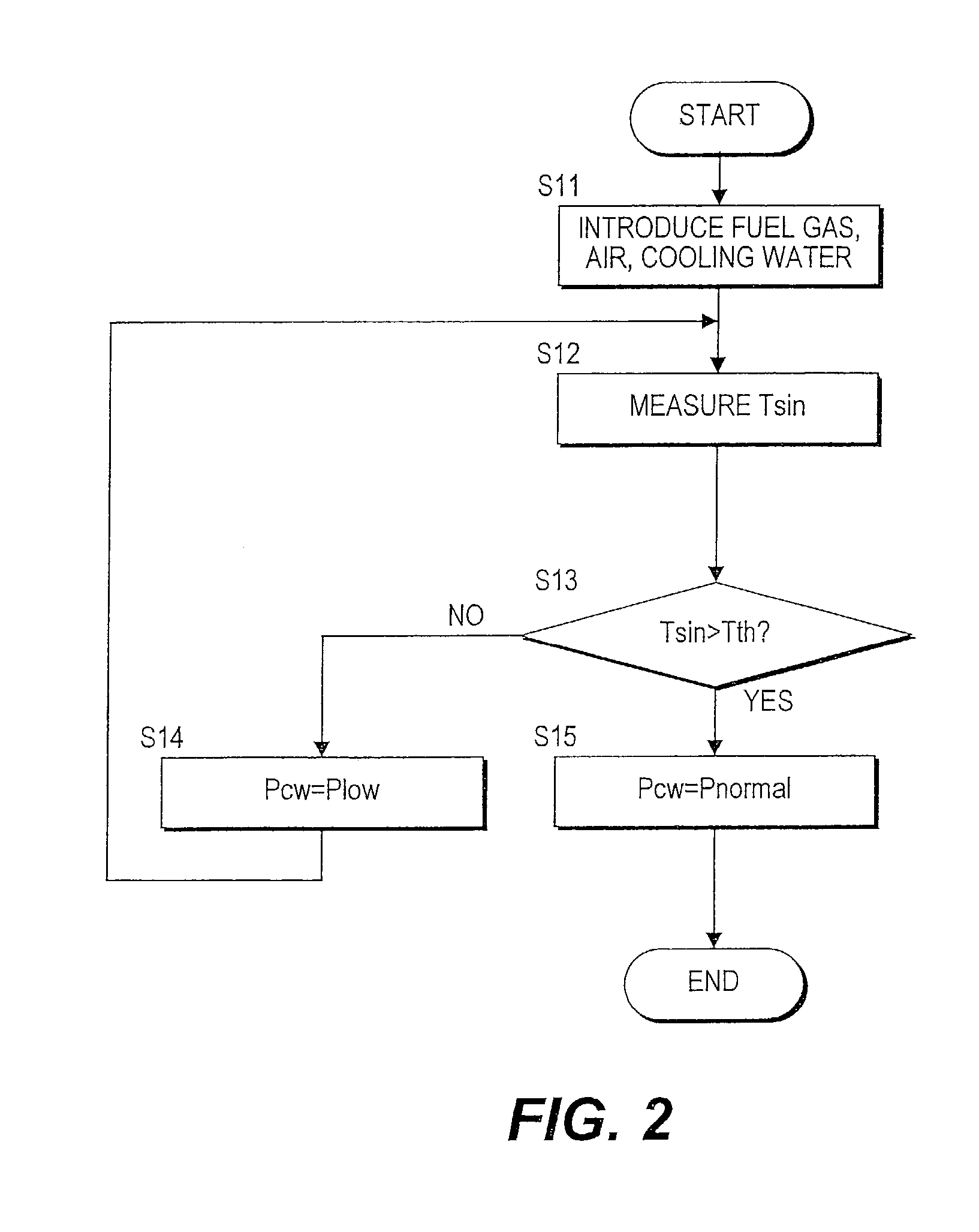
[0042]Moreover, the startup processings of the system performed by the controller 16 is also different. The controller 16 predicts water clogging from the temperature distribution of the cells, and performs pressure control of cooling water. The average of the cell temperatures is calculated, and the cooling water pressure Pcw is also controlled based on the differential pressure ΔP between the cooling water and the electrodes 2, 3 (cathode 2 and anode 3) at the inlet of the fuel cell stack, and the average Tcelave of cell...

third embodiment

[0052]Next, this invention will be described.

[0053]FIG. 6 shows the construction of the fuel cell system of the third embodiment. This is essentially identical to the construction of the first embodiment, however temperature sensors 31, 32 are formed in the cooling water passage 9 near the inlet and outlet of the fuel cell stack 1, respectively. Also, the startup processing of the system performed by the controller 16 is also different.

[0054]The controller 16 calculates a temperature difference ΔT of the cooling water between the fuel cell inlet and outlet. From this temperature difference ΔT, the reaction status inside the fuel cell stack 1 can be grasped, water clogging can be estimated and cooling water pressure control performed. The temperature difference ΔT can be measured by installing temperature sensors 31, 32 at the fuel cell inlet and outlet, respectively, as shown in FIG. 6, or by installing a thermocouple in the cooling water passage 9. In both cases, temperature measur...


PUM


Abstract

Before warmup of a fuel cell stack (1) is complete, a cooling water pressure of the fuel cell stack (1) is suppressed lower than the pressure used when the fuel cell system is run in the steady state. In this way, when the system is started from a low temperature state, water in a cathode (2) and anode (3) flows efficiently into the cooling water passage (9), and water clogging is prevented while maintaining a proper water balance in the fuel cell system.

Description

FIELD OF THE INVENTION[0001]This invention relates to a fuel cell system, and more particularly to startup control when a fuel cell system is started from a low temperature state.BACKGROUND OF THE INVENTION[0002]A fuel cell system transforms the energy of fuel, directly into electrical energy. In the fuel cell system disclosed by JP8-106914A published by the Japanese Patent Office in 1996, in a pair of electrodes provided on either side of a membrane electrode, fuel gas containing hydrogen is supplied to the anode and an oxidizing agent gas containing oxygen is supplied to the cathode. Electrical energy is then extracted from the electrodes, using the electrochemical reactions produced on the surface of the membrane electrode, i.e.,[0003]anode reaction: H2→2H++2e−[0004]cathode reaction: 2H++2e−+(½)O2→H2O[0005]The fuel gas supplied to the anode, may be supplied directly from a hydrogen storage device, or fuel containing hydrogen may be reformed, and the reformed hydrogen-containing g...

Claims


Application Information

Patent Timeline
IPC IPC(8): H01M8/04H01M8/02H01M8/24
CPCH01M8/023H01M8/04074H01M8/04253H01M8/04768H01M8/04365Y02E60/50H01M8/04395H01M8/04417H01M8/24H01M8/04388H01M8/04223H01M8/04225H01M8/04302
Inventor TAKAHASHI, SHINICHIYOSHIZAWA, KOUDAI
Owner NISSAN MOTOR CO LTD
Why Eureka
Try Eureka