Primary side ZVS push-pull converter having relatively less losses

a push-pull converter and push-pull technology, which is applied in the field of push-pull converters, can solve the problems of increasing the number of switches, the complexity of the control of the circuit, and the requirements regarding the efficiency of the system are relatively high, so as to improve the efficiency of the ups system and reduce the switching losses of the circui

Active Publication Date: 2006-05-23
DELTA ELECTRONICS INC
View PDF1 Cites 11 Cited by
  • Summary
  • Abstract
  • Description
  • Claims
  • Application Information

AI Technical Summary

Benefits of technology

[0019]It is therefore an object of the present invention to propose a push-pull converter having primary side switches for zero-voltage switching so as to decrease the switching losses of the circuit and to improve the efficiency of the UPS system.
[0028]Preferably, the leaking inductance between the primary winding and the secondary winding of the transformer is relatively larger and the two windings of the primary winding are coupled to each other relatively good.

Problems solved by technology

Since the capability of a battery to supply the electrical power is limited, thus the requirements regarding the efficiencies of the systems are relatively higher.
But, the number of switches is increased and the control of the circuit is relatively more complex.
Thus, this circuit is not desirable for the cost-concerned applications.2. ZVS LCL-Resonant Push-Pull ConvertersPlease refer to FIG. 2, it shows the schematic circuit diagram of a LCL-resonant push-pull converter.
Besides, there are tradeoffs regarding the choosing of the CL elements of these converters even though the switching frequency and the leakage inductance are given.
Otherwise, the conduction losses could be relatively higher.

Method used


Image

  • Primary side ZVS push-pull converter having relatively less losses
  • Primary side ZVS push-pull converter having relatively less losses
  • Primary side ZVS push-pull converter having relatively less losses

Examples


Embodiment Construction

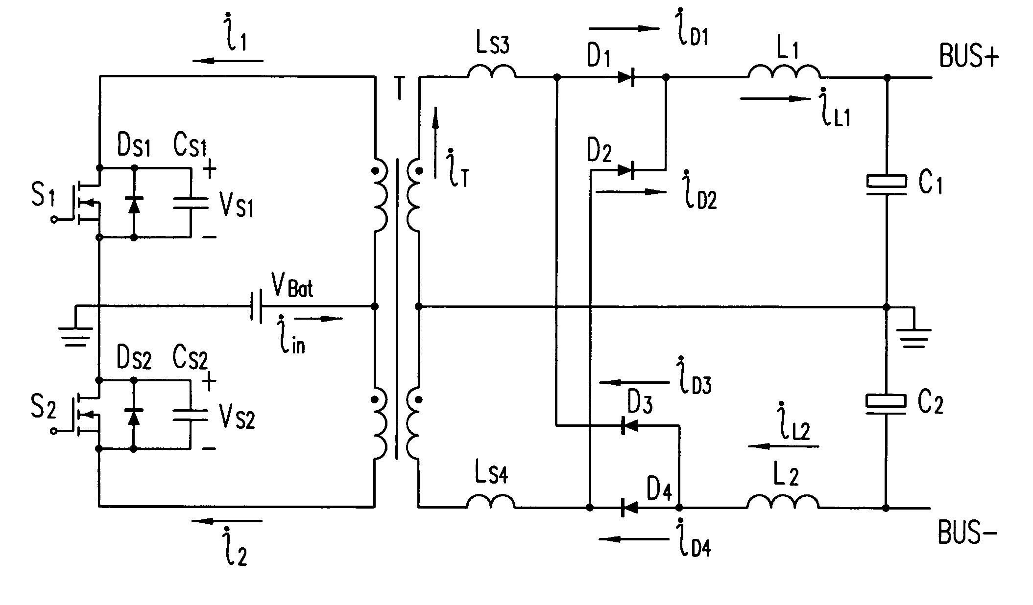
[0045]After studying the discharging features of the batteries, a unique set of operational modes especially suitable for the DC—DC converter in the UPS system is elaborated in the present invention firstly. According to these operational modes, a method is proposed, in which the exciting current of the transformer is employed to accomplish the zero-voltage switching of the switches at the primary side of the push-pull converter when the UPS system has a relatively heavy load or the UPS system has a light load but the battery is at the late stage of the discharge, to decrease the switching losses of the proposed ZVS push-pull converter and to increase the efficiency of the UPS system relatively.

[0046]For a DC—DC converter disposed on the UPS system, the voltage regulation of its' outputs within certain range is not necessary since the output voltage regulation of the UPS system could be guaranteed by the inverter in the second stage circuit. According to this concept, a unique set o...


PUM


Abstract

The push-pull converter for zero-voltage switching of the switches on the primary side of the transformer to have a relatively lower loss is proposed. Which includes: a transformer having a primary winding with a center tap and a secondary winding, an electrical energy storage device having a first terminal coupled to the center tap of the primary winding and a second terminal coupled to a ground, a first switch having a first terminal coupled to a first terminal of the primary winding and a second terminal coupled to the ground, a second switch having a first terminal coupled to the ground and a second terminal coupled to a second terminal of the primary winding, and a rectifier circuit coupled to the secondary winding for transforming an AC output of the secondary winding to a DC output.

Description

FIELD OF THE INVENTION[0001]The present invention relates to the improvements of the push-pull converter. More specifically, this invention relates to the push-pull converter having primary side switches for zero-voltage switching (ZVS) so as to decrease the losses and to improve the efficiency.BACKGROUND OF THE INVENTION[0002]For the on-line uninterruptible power supply (UPS) systems, there are in general three working modes: the on-line mode, the battery mode, and the bypass mode. In the dual-mode, a power supply is offered to the load by a battery and through a DC—DC converter and an inverter. Usually, the DC voltage values offered by the battery are transformed and boosted to the DC voltage values required by the DC Bus through the DC—DC converter, and the DC voltage values of the DC Bus are transformed to the AC voltage outputs through the inverter.[0003]Limited by the voltage values of the single battery, the battery set of the UPS system is usually composed by series connecte...

Claims


Application Information

Patent Timeline
Patent Type & Authority Patents(United States)
IPC IPC(8): H02J7/00H02M3/335H02M7/519
CPCH02M3/33569H02M3/33592Y02B70/1491Y02B70/1475H02M2001/0048Y02B70/10H02M1/0048H02M3/01
Inventor YING, JIANPINGLIN, HUAZHU, QIUHUATSAI, WEN-YIN
Owner DELTA ELECTRONICS INC
Why Eureka
Try Eureka