

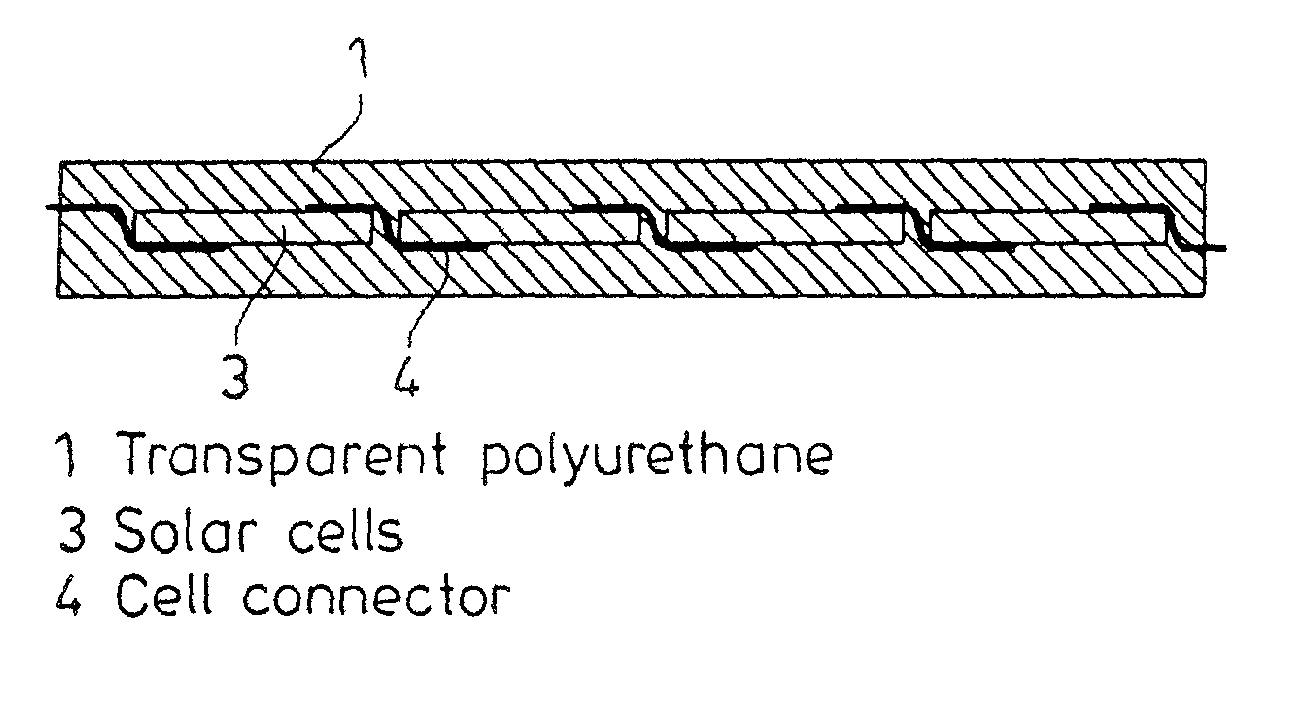
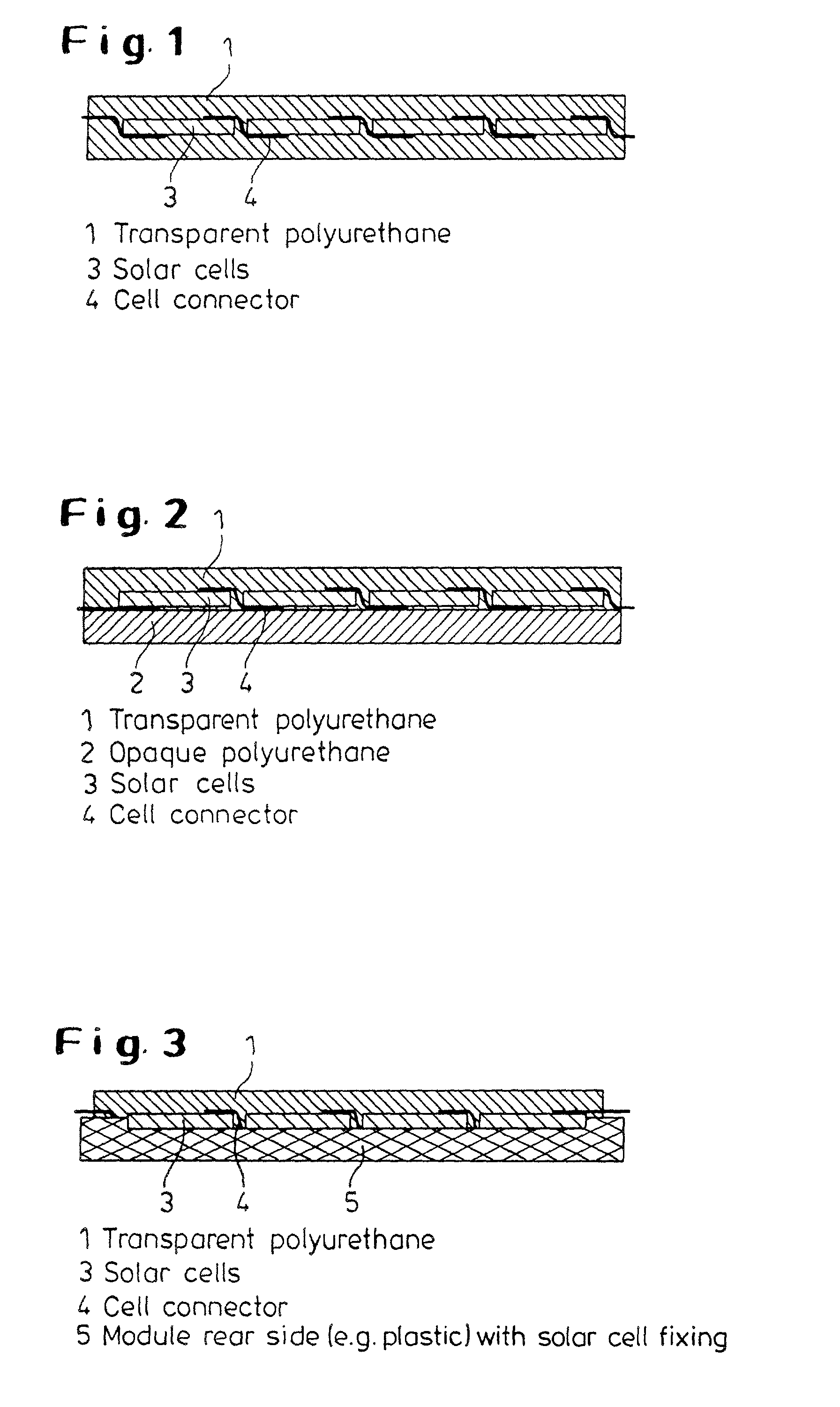
Solar modules with a transparent polyurethane front side and a process for producing same
a technology of solar modules and polyurethane, which is applied in the direction of process and machine control, electric variable regulation, instruments, etc., can solve the problems of corroding metal contacts, chemical degradation of eva embedding materials, and complete failure of modules, so as to achieve rapid, simple and cost-effective methods, and low weight
- Summary
- Abstract
- Description
- Claims
- Application Information
AI Technical Summary
Benefits of technology
Problems solved by technology
Method used
Image

Examples
example 1
[0049]Solar cells encapsulated by means of transparent polyurethane were produced by a RIM (“reaction injection molding”) process. For test purposes, two solar cells, each with an area of approx. 5×5 cm2, were soldered to one another. The solar cells were first positioned in the mold on supports. After closure of the mold, the reaction mixture, Bayflex® VP.PU 14IF02 / VP.PU 18IF11 (available from Bayer AG), was injected and flowed around the solar cell in which the supports had been included.
[0050]The transparent polyurethane system (Bayflex® VP.PU 14IF02 / VP.PU 18IF11 available from Bayer AG) included an aliphatic polyisocyanate (low-viscosity HDI-trimer, viscosity at 23° C. 1200 mPa·s, NCO content 23%, monomeric HDI 3) and a short-chain polyester polyol (viscosity at 23° C. approx. 1900 mPa·s, hydroxyl content 16% or hydroxyl value 528, water content 3). 1% of dibutyl-tin-dilaurate (DBTL), based on total amount of system, was used as the catalyst.
[0051]In preliminary tests, a glass f...
example 2
[0055]In this example, a casting process was to encapsulate to solar cells (each having an area of approximately 5×5 cm2) soldered to each other in transparent polyurethane. A glass fiber reinforced polycarbonate plate (thickness approx. 3 mm) served as the rear side. The solar cells were fixed to the rear side by means of adhesive. Alternatively, the shaping of the rear side could be used to fix the solar cells (e.g., by means of depressions). After the solar cells had been fixed, the transparent polyurethane system was cast onto the solar cells. At the same time, a homogeneous mixing of the two components was accomplished with a suitable mixhead. A reaction mixture available from Rheinchemie GmbH was used. This reaction mixture included an aliphatic polyisocyanate commercially available under the designation RC-DUR 302 (HDI trimer, biuret compound, viscosity at 23° C. approx. 2500 mPa·s, NCO content 23%, monomeric HDI 3) and a caprolactone polyol commercially available under the d...
PUM
| Property | Measurement | Unit |
|---|---|---|
| transmittance | aaaaa | aaaaa |
| thick | aaaaa | aaaaa |
| thick | aaaaa | aaaaa |
Abstract
Description
Claims
Application Information