Optical metrology tool having improved contrast

a contrast and optical metrology technology, applied in the field of optical metrology, can solve the problems of increased measurement error, reduced throughput and resolution, and no conventional practice is completely satisfactory for small-spot optical spectroscopic measurement systems, so as to improve contrast, minimize edge effects, and improve system performance

Inactive Publication Date: 2006-05-23
THERMA WAVE INC
View PDF13 Cites 12 Cited by
  • Summary
  • Abstract
  • Description
  • Claims
  • Application Information

AI Technical Summary

Benefits of technology

[0013]The subject of this invention is a family of optical designs for a metrology system wherein the beam-control apertures are selected and arranged such that the relative numerical aperture, NAR≡NAI/NAC<1. Tailoring the partial coherence of the optical system using beam-controlling apertures in this manner enhances system perform

Problems solved by technology

Some of the difficulties in practice are:(a) The optics must accommodate ever-smaller feature size [critical dimension] and tighter position [overlay] requirements, for specific materials.(b) The optics must precisely locate the test feature boundaries, since any light falling on the surrounding features and collected by the detector can cause measurement error.(c) The optics between the source and detector must minimize the radiation falling on or detected from areas outsid

Method used


Image

  • Optical metrology tool having improved contrast
  • Optical metrology tool having improved contrast
  • Optical metrology tool having improved contrast

Examples


Embodiment Construction

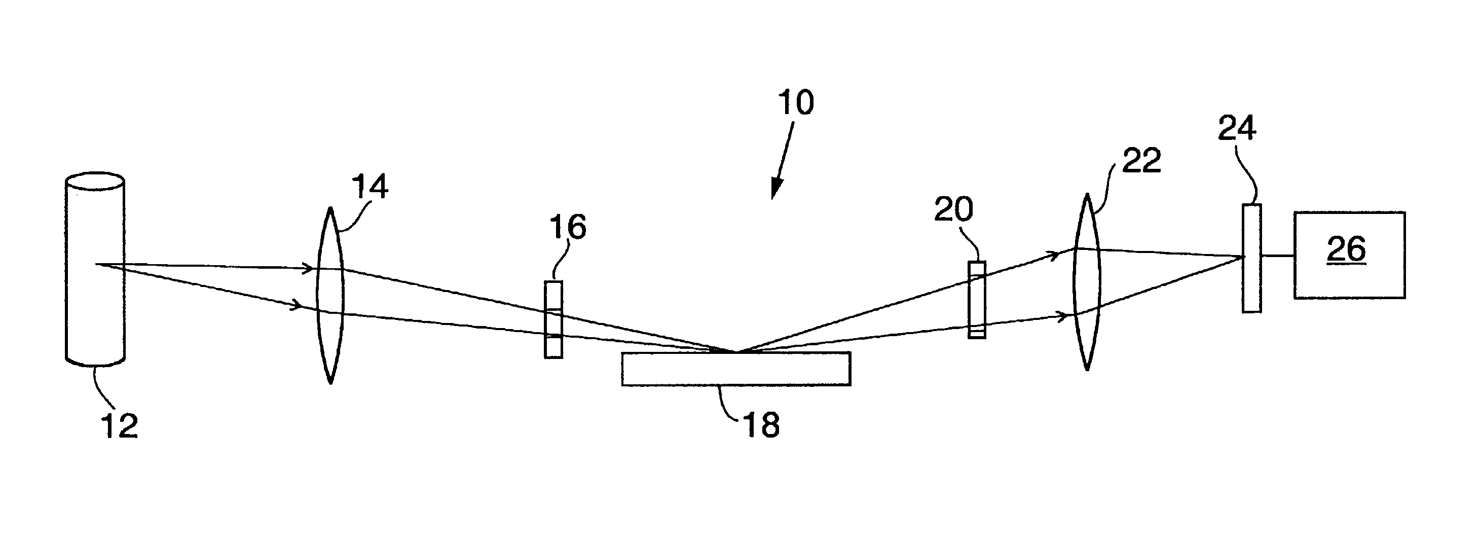
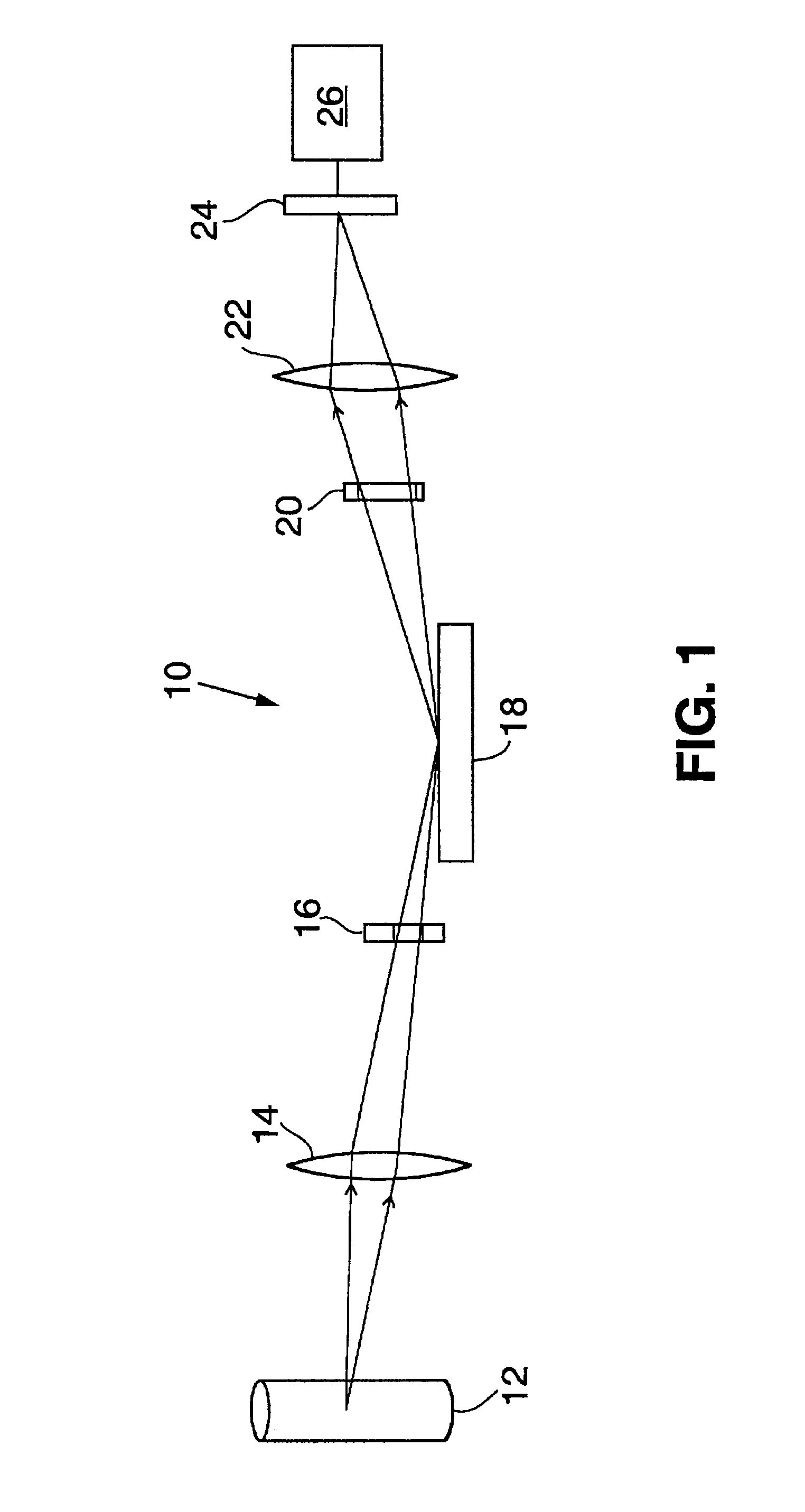
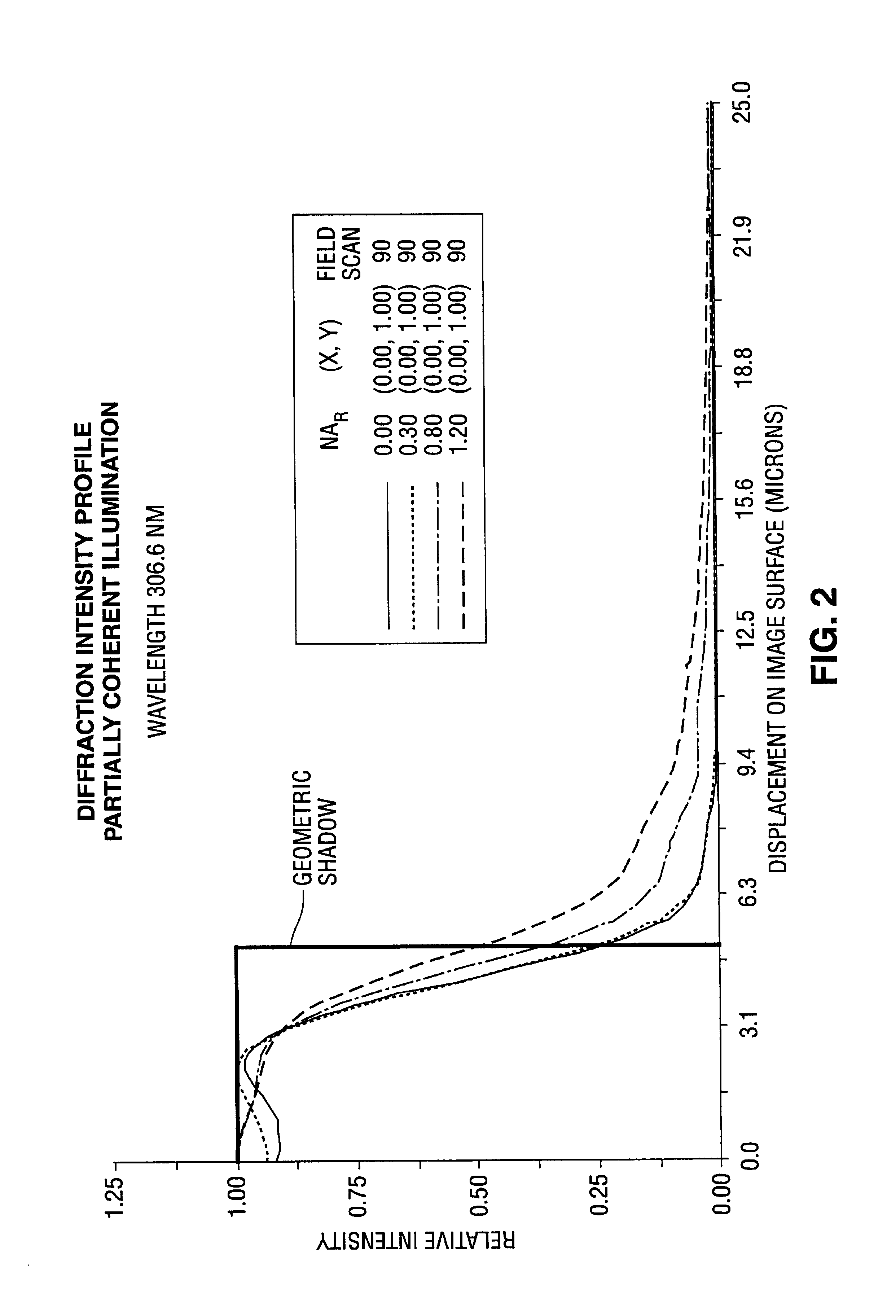
[0018]As discussed above, the common practice in the art is to design instruments wherein the relative numerical aperture, NAR=NAI / NAC≧1. The NAR is the ratio of the angular acceptance of the illuminator to the angular acceptance of collection optics, and is a direct measure of the partial coherence of the system; e.g. NAR.=0, implies fully coherent illumination, NAR>>1 implies incoherent illumination. The subject invention is particularly useful for a family of optical designs for broadband optical systems wherein the beam-control apertures are selected such that NAR<1. The optical designs are applicable to a large class of broadband optical instruments commonly utilized in wafer metrology employing, spectrophotometry, spectroscopic reflectometry, spectroscopic ellipsometry and including spectroscopic scatterometry techniques. The benefits of the subject invention are not limited to broadband systems but are also applicable to inspection devices that use incoherent light to illumin...


PUM


Abstract

The subject invention relates to broadband optical metrology tools for performing measurements of patterned thin films on semiconductor integrated circuits. Particularly a family of optical designs for broadband optical systems wherein the ratio of illumination system to collection system numerical apertures is less than 1. System performance is enhanced through selection and control of the optical system partial coherence; this is accomplished through installation of beam-control apertures within the illumination and collection optical systems. The invention is broadly applicable to a large class of broadband optical wafer metrology techniques including spectrophotometry, spectroscopic reflectometry, spectroscopic ellipsometry and spectroscopic scatterometry.

Description

PRIORITY CLAIM[0001]The present application claims priority to U.S. Provisional Patent Application Serial No. 60 / 349,672, filed Jan. 16, 2002, which is incorporated herein by reference.TECHNICAL FIELD[0002]The subject invention relates to the field of optical metrology, particularly broadband optical metrology tools for performing measurements of patterned thin films on semiconductor integrated circuits.BACKGROUND OF THE INVENTION[0003]A number of metrology tools are now available for performing optical measurements on semiconductors. Such tools can include spectroscopic reflectometers and spectroscopic ellipsometers. Examples of such tools can be found in U.S. Pat. Nos. 5,608,526 and 6,278,519, both incorporated by reference. Such tools typically include a broadband light source for generating a probe beam that is directed to reflect off the sample. Changes in intensity or polarization state of the beam as a function wavelength are monitored to yield information about the sample.[0...

Claims


Application Information

Patent Timeline
IPC IPC(8): G01N21/00G01N21/95G01N21/956
CPCG01N21/9501G01N21/956G01N2021/213
Inventor OPSAL, JONWANG, DAVID Y.
Owner THERMA WAVE INC
Why Eureka
Try Eureka