Optical coupling device for single mode optical fibers

a single-mode optical fiber and coupling device technology, applied in the direction of optical waveguide light guide, optical elements, instruments, etc., can solve the problems of limited diffraction of focused radiation spots, large number of optical amplification systems, and large number of laser sources, and achieve the effect of maximizing energy transfer efficiency

Inactive Publication Date: 2006-05-30
APPLIED OPTICS CENT OF DELAWARE
View PDF17 Cites 0 Cited by
  • Summary
  • Abstract
  • Description
  • Claims
  • Application Information

AI Technical Summary

Benefits of technology

[0011]There is, therefore, provided in accordance with the present invention an integral solid state, radiation coupler comprising a radiation input end and a radiation output end said radiation input end connected to said radiation,output end through two diverging and two converging radiation paths wherein said radiation paths converge to said output end at an angle 2θ. θ is an interference angle calculated to produce an exiting radiation interference pattern of radiation enter

Problems solved by technology

This necessitates using higher power, and therefore cost laser sources and/or using a large number of expensive and cumbersome optical amplification systems including additional pump lasers, Erbium Doped fibers, couplers, gain flattener, optical filters, polarization controllers to compensate for the losses due to the low coupling efficiency.
The more customary coupling m

Method used


Image

  • Optical coupling device for single mode optical fibers
  • Optical coupling device for single mode optical fibers
  • Optical coupling device for single mode optical fibers

Examples


example

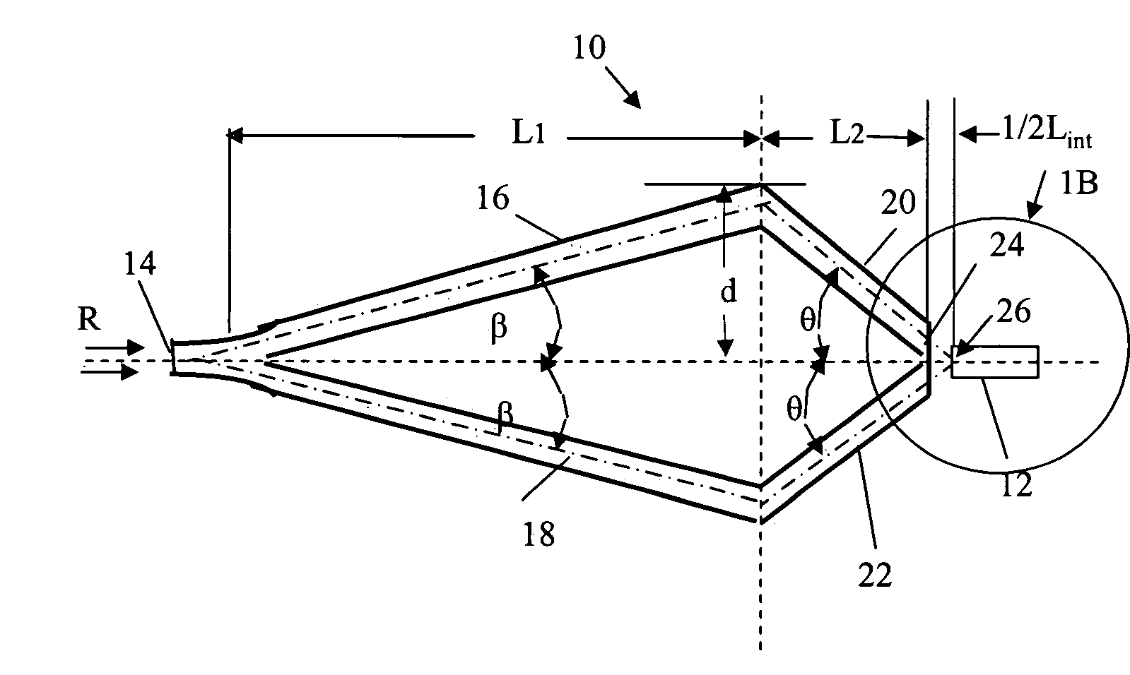
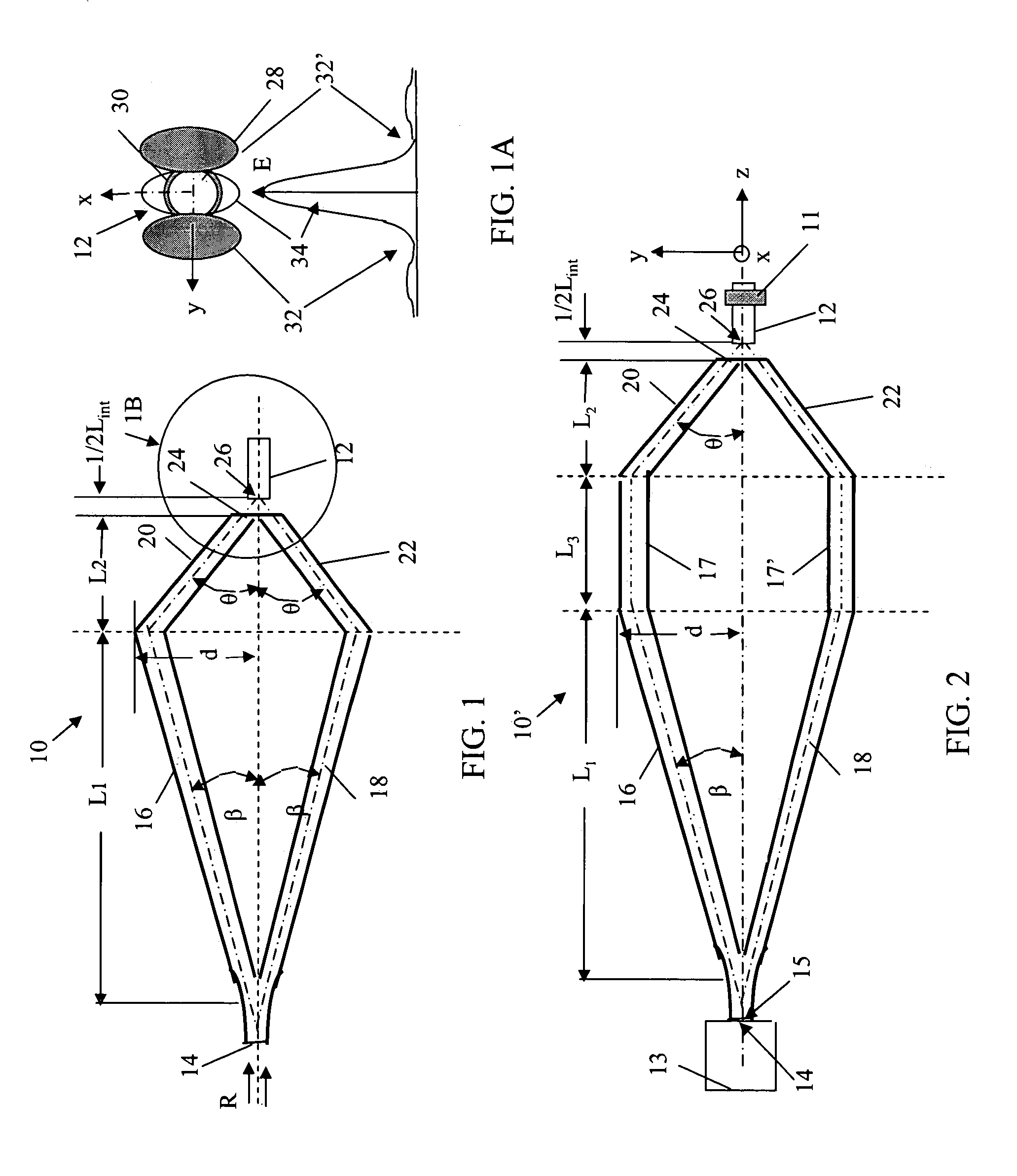
[0053]Using the calculations shown in the appendix the following results are obtained for a coupler such as illustrated in FIG. 1, the length of the channels 16, 18, 20 and 22 and the diverging and converging angles β and θ for a particular type of single mode fiber, specifically a Corning SMF 28. This fiber has a typical MFD=8.2 μm and a NA=0.14. For this fiber and at λ=1550 nm, V=2.33. For an input (to the fiber) beam waist ω0=8.1 μm, V×ω0=18.87 μm, yielding an optimum interference angle (converging angle θ) of about 2.9°.

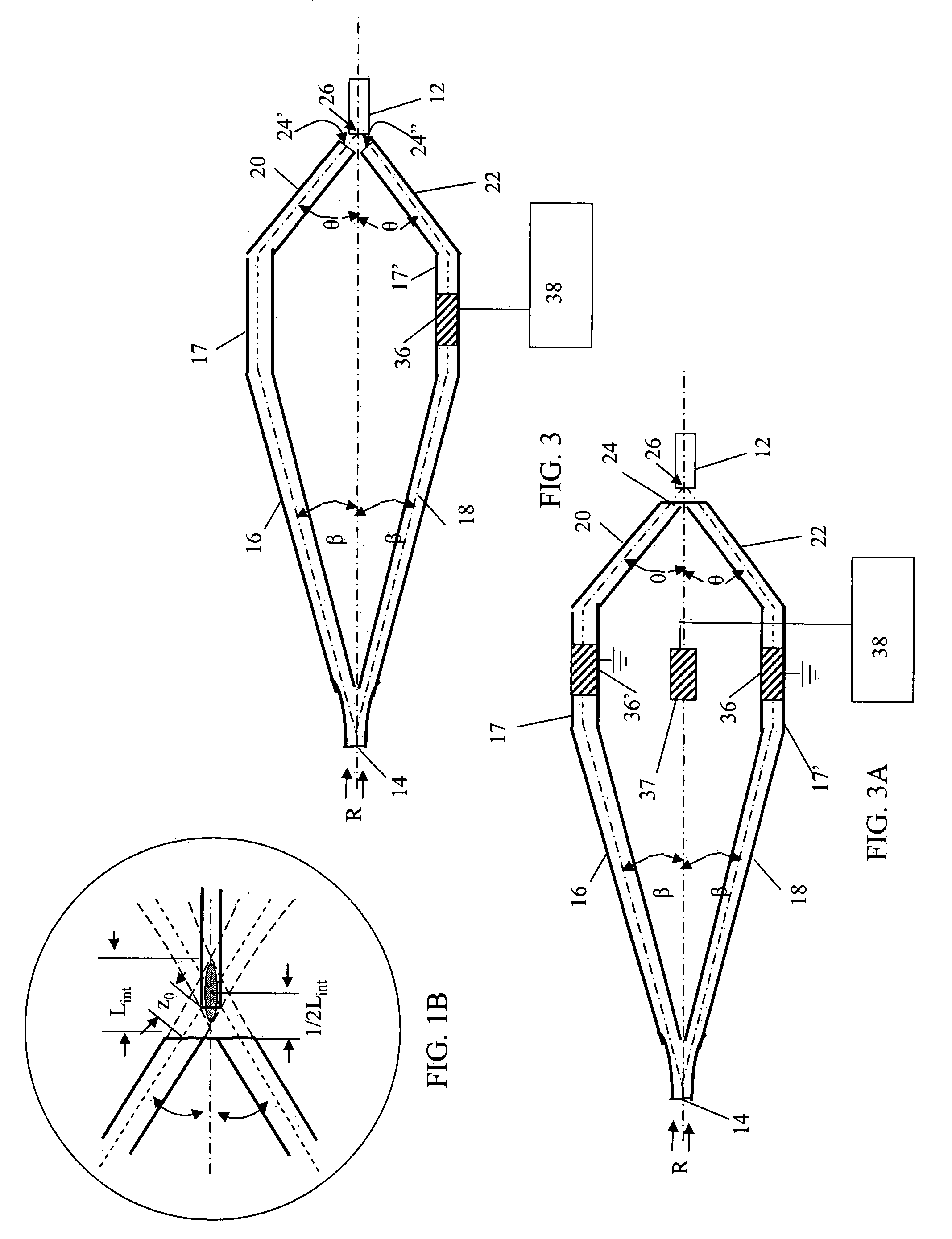
[0054]The interference is localized where the two output beams cross as illustrated in FIG. 1B. Having determined the converging angle, simple geometrical considerations from FIG. 1B indicate that the input end of the single mode fiber 12 (in this example the input face of SMF28) may be placed anywhere between +1 / 2Lint and −1 / 2Lint from the crossing point, in this instance a total Lint=162 μm.

[0055]Having defined the interference zone, it is noted that maximum en...


PUM


Abstract

A device for coupling incident radiation to a single mode fiber optic a solid state interferormeter having a front end similar to a Mach-Zehnder integrated interferometer and a back end formed by two converging radiation channels converging at an angle θ and terminating prior to overlapping. The angle θ is calculated to produce an interference zone formed by the exiting radiation a primary constructive interference fringe that provides an optimum match to an input fiber mode of a fiber positioned within the interference zone.

Description

CROSS REFERENCE TO RELATED APPLICATIONS[0001]This application claims the benefit of priority to U.S. Provisional Application No. 60 / 454,990, filed on Mar. 14, 2003, and application Ser. No. 60 / 472,968, filed on May 23, 2003, both the contents of which are incorporated, herein by reference in their entirety.[0002]This application is also related to United States application filed concurrently herewith entitled “Interferometric analog optical modulator for single mode fibers,” serial number unknown.FIELD OF THE INVENTION[0003]This invention relates to apparatus and associated method for coupling the output of an optical radiation source to a single mode optical fiber or optical wave-guide and more particularly to apparatus and associated method employing divergent / convergent optical beam paths to form a constructive interference pattern at an optical input of a single mode fiber or optical wave-guide thereby to couple said fiber or waveguide to said source.BACKGROUND OF THE INVENTION[...

Claims


Application Information

Patent Timeline
IPC IPC(8): G02F1/035G02B6/24H01S3/10G02B6/12G02B6/125G02B6/30G02F1/225
CPCG02B6/12007G02B6/30G02B6/125G02F1/225
Inventor MELIKECHI, NOUREDDINEAMARA, KAMEL
Owner APPLIED OPTICS CENT OF DELAWARE
Why Eureka
Try Eureka