Piston assembly for a compressor

a compressor and piston technology, applied in mechanical equipment, machines/engines, positive displacement liquid engines, etc., can solve the problems of not allowing screws or bolts to be secured therein, the driving mechanism of the compressor and the pistons are especially difficult to mount, and the mounting space needs to be provided, so as to achieve the effect of optimizing the thickness of the wall

Inactive Publication Date: 2006-06-06
VALEO SYST THERMIQUES
View PDF26 Cites 2 Cited by
  • Summary
  • Abstract
  • Description
  • Claims
  • Application Information

AI Technical Summary

Benefits of technology

[0011]The object of the present invention is to provide a compressor and a piston for use in such a compressor in which anti-rotation locking is provided but which also enables the compressor to be made small and lightweight, with a front casing that has a wall thickness optimized in the respect of its weight and bulk. The aforementioned problems described initially with regard to the size of a compressor for use with CO2 as the refrigerant can therefore also be mitigated.

Problems solved by technology

In essence, the two trends conflict because the use of CO2 as the refrigerant in the compressor requires it to operate at a higher pressure than a conventional system using R134a as a refrigerant and this leads to the requirement for the compressor to be made from high pressure components, such as steel, which is heavier than materials such as aluminum that can be used to manufacture compressors for use at lower pressures.
However, the design of the casing is such that the driving mechanism of the compressor and the pistons especially are difficult to mount.
To keep the weight of the compressor to a minimum, its casing has a low wall thickness but this does not allow screws or bolts to be secured therein.
However, this requires mounting space to be provided.
Consequently, the compressor in question tends to be bulky.
The weight of the compressor is also added to by the fact that a considerable number of very lengthy bolts is required.
A further drawback of the compressor is that each bolt must be individually sealed because its head projects out of the casing.
As sealing of particularly high pressures in the vicinity of the bold head is required, this problem can be severe.
A further problem arises in swash or wobble plate compressors relating to the requirement to prevent the plates from rotating during use.
Consequently, owing to contact between the enlarged bridge portion and the inner wall surface of the casing which occurs as a result of rotation of the piston during use, the actual degree of the rotation is limited.
However, this arrangement has the significant disadvantage that the guide length of the piston body is reduced.

Method used


Image

  • Piston assembly for a compressor
  • Piston assembly for a compressor
  • Piston assembly for a compressor

Examples


Embodiment Construction

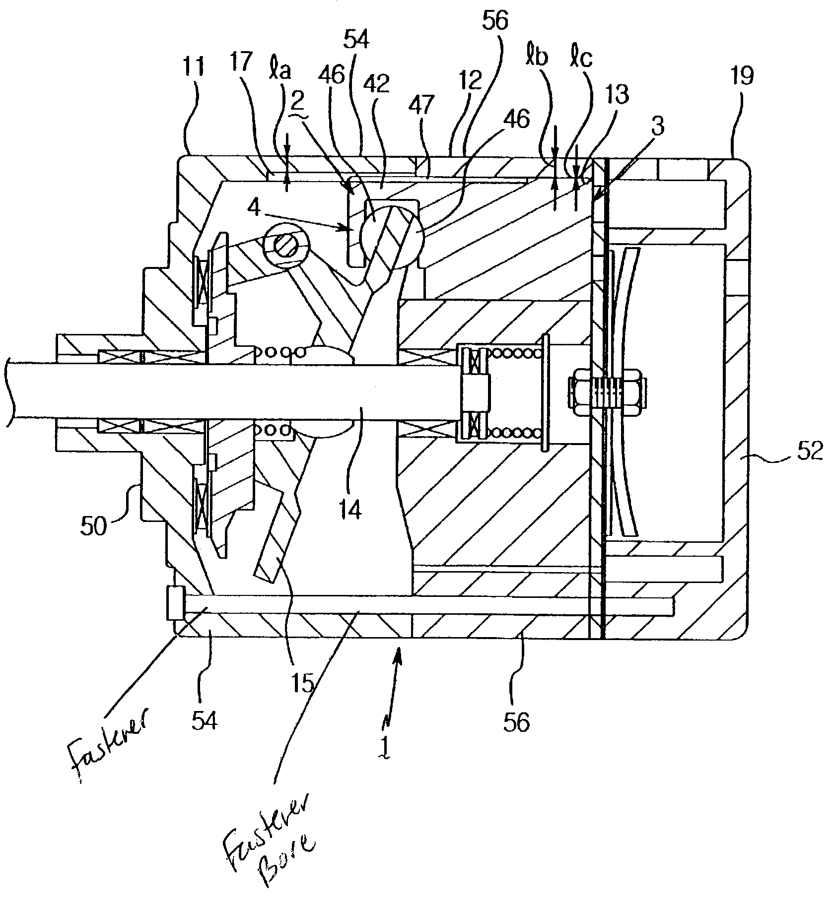
[0041]Referring firstly to FIG. 2, a front casing 10 for the use in a compressor according to the invention comprises a cylindrical portion 11 and an end plate 12 which is connected to the cylindrical portion by screw fasteners, as will be described. It will be appreciated, however, that the front casing could be made of unitary construction with cylindrical portion 11 and end plate 12 made in one piece in a “cup-shaped” design. Alternatively, end plate 12 could be welded to cylindrical portion 11 to provide the same effect.

[0042]Cylindrical portion 11 has an inner wall surface that has two different diameters and therefore defines a plurality of longitudinally extending recesses 13. Recesses 13 are equally distributed around the inner circumference of cylindrical portion 11 and their number corresponds to the number of pistons 14 (see FIGS. 3 and 4) to be accommodated in casing 10.

[0043]Wall surface 15a between recesses 13 defines the smaller of the inner diameters of front casing ...


PUM


Abstract

A compressor for a vehicle air conditioning system comprises a front casing in which is mounted a swash or wobble plate arrangement operatively connected to a drive shaft and a plurality of pistons each provided with a piston body at one end and a foot portion at its other. A cylinder block is also provided defining a plurality of cylinder bores equally distributed circumferentially around the drive shaft, in each of which bores one of the piston bodies can be reciprocated by the swash or wobble plate, as the drive shaft rotates. The inner wall surface of the front casing defines a plurality of longitudinally extending recesses in positions apposed to each piston. The piston body and the foot portion of each piston are connected by a bridge that is bending resistant and projects outwardly into these apposed recesses. Also, at least one side of the bridge is provided with a laterally projecting wing that supports the piston against the adjacent inner wall surface of the front casing to one side of the recess. The front casing and the pistons are thus designed for mutual interengagement and, in the piston, the requirement to provide a bending resistant portion has been divided away from the requirement to provide an anti-rotation locking arrangement.

Description

FIELD OF THE INVENTION[0001]The present invention relates to a swash or wobble plate compressor, in particular a CO2 compressor; for a vehicle air-conditioning system, and to piston for use in such a compressor.BACKGROUND OF THE INVENTION[0002]Currently, there are two main trends in the design and manufacture of compressors for use in vehicle air-conditioning systems. These are the use of the more environmentally friendly carbon dioxide (CO2) as a refrigerant to replace tetrafluoroethane (R134a) and the refrigerant for smaller, lightweight compressors which take up as little space and have as low a weight as possible. The latter trend arises as a result of the desire to produce smaller and lighter vehicles which are more fuel efficient. It is also a requirement that the compressor itself be energetically efficient.[0003]In essence, the two trends conflict because the use of CO2 as the refrigerant in the compressor requires it to operate at a higher pressure than a conventional syste...

Claims


Application Information

Patent Timeline
Patent Type & Authority Patents(United States)
IPC IPC(8): F04B1/12F04B27/08F04B27/10
CPCF04B27/1081F04B27/0878
Inventor SCHWARZKOPF, OTFRIEDREU.BETA., MARKUS
Owner VALEO SYST THERMIQUES
Why Eureka
Try Eureka