Drug delivery platform

a technology of a delivery platform and a delivery plate, which is applied in the field of delivery plates, can solve the problems of dramatically accelerated in-stent restenosis rates of arteries treated with stents, limiting both utilization and long-term clinical benefits

Inactive Publication Date: 2006-06-06
THE BOARD OF TRUSTEES OF THE LELAND STANFORD JUNIOR UNIV
View PDF14 Cites 73 Cited by
  • Summary
  • Abstract
  • Description
  • Claims
  • Application Information

AI Technical Summary

Benefits of technology

[0010]Compositions and methods are provided for a stent based drug delivery system. The stent comprises a matrix, where the matrix has entrapped a pharmaceutical agent of interest. The matrix, for example microspheres, etc. resides within a channel formed on one or both of the abluminal or adluminal surfaces of the stent, and allows for release, usually sustained release, of the entrapped agent. The stent and matrix is encased with a gel covalently bound to the stent surface and optionally also covalently bound to the matrix, which prevents loss of the matrix during transport and implantation of the stent, and which affects the release of the biologically active agent, through degradation and diffusion characteristics.
[0012]The delivery system of the invention also find use in the evaluation of candidate agents by providing both efficient delivery and low perturbation at the site of implantation. The efficiency of drug delivery provided by the drug delivery stent allows a sensitive comparison of the effect of an agent on, for example, restenosis, hyperplasia, and the like.

Problems solved by technology

However, arteries treated with stents also encounter dramatically accelerated rates of in-stent restenosis, which are clinically significant in up to 40% of cases.
In-stent neointima formation thus remains a major procedural limitation for stent use, limiting both utilization and long-term clinical benefits.

Method used


Image

  • Drug delivery platform
  • Drug delivery platform
  • Drug delivery platform

Examples


example 1

Stent-based Local Delivery Platform

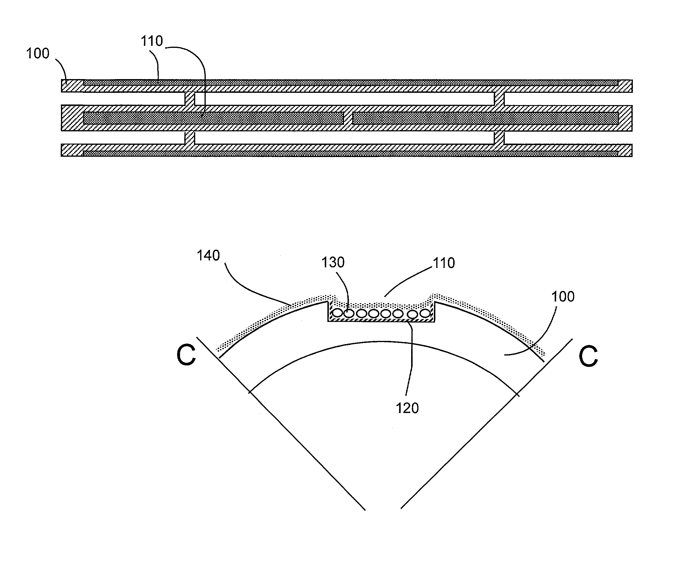
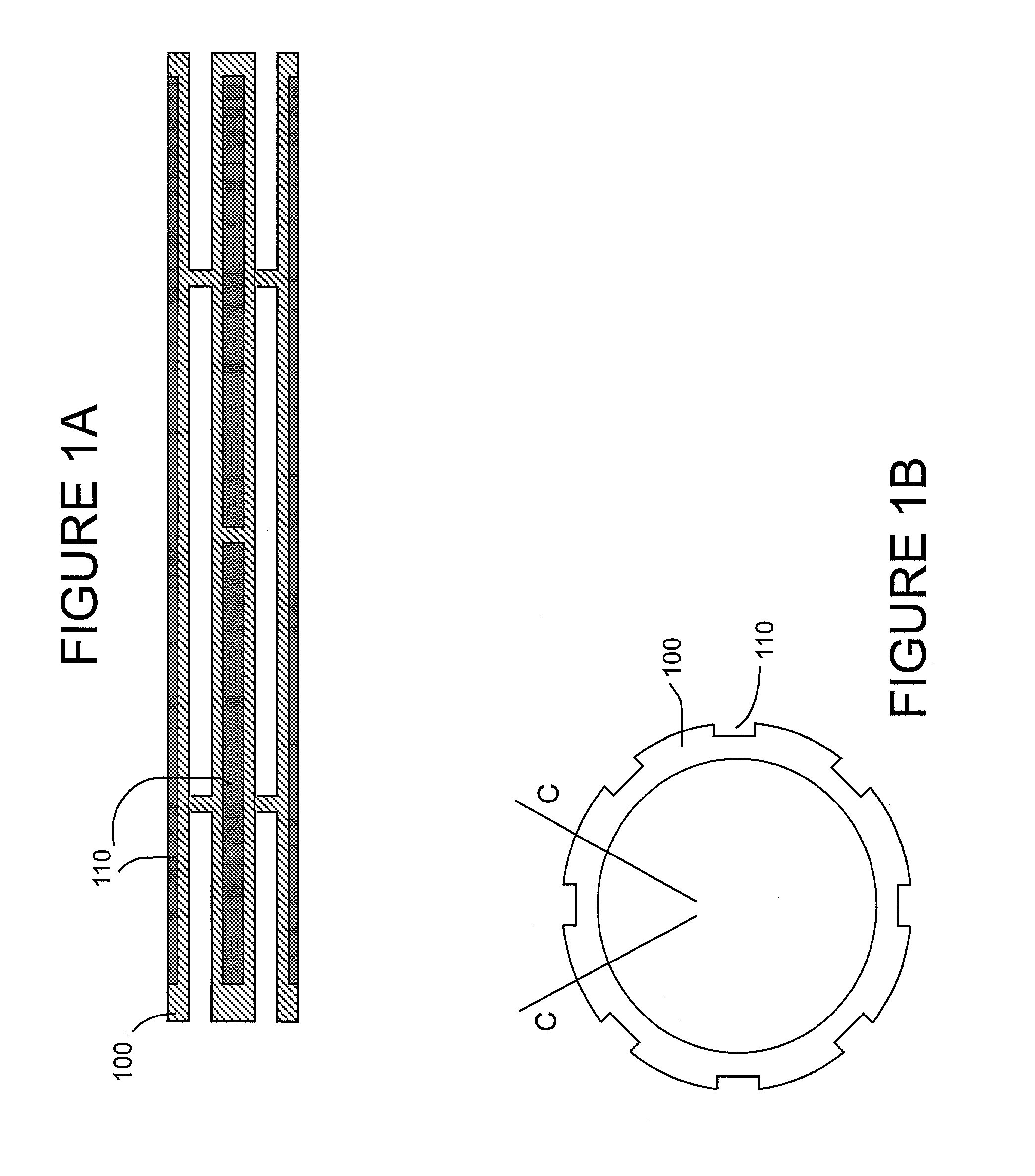
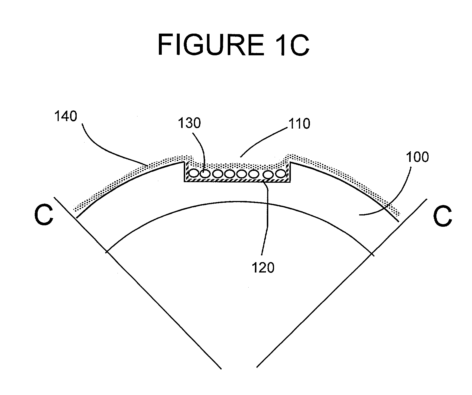
[0089]Stent Design and Loading.

[0090]The stent design for this initial example is based on the Palmaz-Schatz coronary stent. The stainless steel stent is 1.6 mm in diameter and 10 mm in length and has 10 longitudinal struts evenly spaced circumferentially, and it is designed to be balloon expandable up to 5 mm diameter. Its basic slotted tube design was modified by electro-discharge machining (EDM) channels 80 microns wide by 60 microns deep along the length of the abluminal (toward the wall) side of each strut. The stent is designed to provide abluminal (toward the wall) but not adluminal (toward the lumen) delivery. With these dimensions, the channels cover 8.5% of the lumen wall area when deployed to a nominal diameter of 3 mm. The channels were machined from end to end in order to allow drug delivery both to the wall and to the tissue surrounding the stent end which both represent critical sights for neointima formation. Microspheres, which can...

example 2

Stent-based Release of an Angiogenesis Inhibitor Limits In-stent Plaque Progression

[0116]Microsphere Preparation.

[0117]Biodegradable poly(lactic-co-glycolic-acid)-polyethylene glycol (PLGA / PEG) microspheres were prepared as a modification of previously described techniques. A mixture of 8:1:PLGA(75:25):PEG-8000 was employed with the double emulsion technique to generate a final microsphere diameter of 10 microns, and a degradation time of approximately 4 weeks. Additionally, a pH buffer of 7.4 was incorporated to limit local pH changes in order to stabilize incorporated drugs and render the microspheres more biocompatible. During the microsphere manufacturing process, 2.0 mg of the angiogenesis inhibitor angiostatin (Calbiochem, La Jolla, Calif.) in 200 ml phosphate buffered saline was added to the polymer solution. Control microspheres (blank microspheres) containing polymer and buffer without any drug were also prepared. Stents were prepared as above.

[0118]In Vivo Stent Implantati...

example 3

Stent-based Release of a Factor to Increase Nitric Oxide Levels can Limit In-stent Plaque Progression

[0128]Microsphere / stent Preparation.

[0129]Microspheres were prepared as above (example 2b) except loaded with 40 mg NOC-12 (Calbiochem, La Jolla, Calif.) in 200 μl phosphate buffered saline in place of angiostatin and stents were loaded as before.

[0130]Plaque Formation.

[0131]Plaque morphometry was assessed as in Example 2, with results summarized as Table 4.

[0132]

TABLE 4Plague formation after in vivo stent implantation and nitric oxide release.Intima to media ratioControl1.981 ± 0.080NO 1.338 ± 0.051*Ratio of intimal area to medial area 28 days after stent implantation for control stents or stents releasing a nitric oxide donor (NO), (mean ± SE),*denotes P = 0.0001 vs. controls.

[0133]Conclusions.

[0134]Stent based local release of a nitric oxide donor reduces plaque progression after stenting. While this example presents use of NOC-12 as a specific agent, any NO donor could be substit...


PUM

PropertyMeasurementUnit
depthaaaaaaaaaa
widthaaaaaaaaaa
diameteraaaaaaaaaa

Abstract

A stent based drug delivery system. A biological agent of interest is entrapped within a matrix, which is loaded into channels on the surface of a stent. The matrix allows for release, usually sustained release, of the entrapped agent. The stent and matrix is sheathed with a covalently bound gel. In one embodiment of the invention, the stent is used to deliver therapeutic agents to a patient, providing the advantage of efficient delivery and sustained release of an agent at a localized site. In another embodiment of the invention, the drug delivery system is used for testing and comparison of candidate drugs in an in vivo setting.

Description

CROSS-REFERENCE TO RELATED APPLICATIONS[0001]This application claims the benefit of priority from U.S. Provisional application No. 60 / 285,383, filed Apr. 20, 2001.BACKGROUND OF THE INVENTION[0002]Stents and other prosthetic devices have provided the means to clinically treat many conditions. Stents are commonly used to open blood vessels, e.g. clearing obstructions, preventing restenosis, providing support at the site of an aneurysm, and to repair damage to vascular tissues, e.g. arteries and veins. In addition to blood vessels, other vessels of the body may be repaired with a stent, including the trachea for breathing disorders, renal and urethral tubules, fallopian tubes for the treatment of infertility, eustachian tubes for the treatment of chronic ear infection and other hearing disorders, large and small intestines where the vessels may be occluded with tumor cells, etc.[0003]Many stent designs are known and in clinical use. For example, they can be cut from a tube or formed fr...

Claims


Application Information

Patent Timeline
Patent Type & Authority Patents(United States)
IPC IPC(8): A61F2/06A61F2/00A61F2/90A61L31/14A61L31/16
CPCA61F2/91A61F2/915A61L31/145A61L31/16A61F2002/91533A61L2300/604A61L2300/416A61F2250/0068B33Y80/00
Inventor ELKINS, CHRISTOPHER J.DAKE, MICHAEL D.WAUGH, JACOB M.
Owner THE BOARD OF TRUSTEES OF THE LELAND STANFORD JUNIOR UNIV
Why Eureka
Try Eureka