Method and device for extraction of electrons in a vacuum and emission cathodes for said device

a vacuum extraction and electron technology, applied in the direction of electron-emitting electrodes/cathodes, discharge tubes cold cathodes, discharge tubes luminescnet screens, etc., can solve the problems of consuming relatively large amounts of energy, dissipating heat, and thermionic emission, and the thermionic technique of emitting electrons does not enable localized electron emission sites to be obtained

Inactive Publication Date: 2006-06-06
UNIV CLAUDE BERNARD LYON 1
View PDF19 Cites 19 Cited by
  • Summary
  • Abstract
  • Description
  • Claims
  • Application Information

AI Technical Summary

Problems solved by technology

That technique is known as thermionic emission and suffers from the drawback of requiring the cathode to be at high temperature (2700 kelvins (K) for a tungsten cathode, for example) and consequently of consuming relatively large amounts of energy and dissipating it as heat.
Furthermore, that thermionic technique of emitting electrons does not enable localized electron emission sites to be obtained.
A drawback of that technique lies in the need to implement a high vacuum (10−10 Torr) in order to stabilize the electron emission current.
Furthermore, in order to obtain an intense electric field, the cathode must necessarily be shaped so present a sharp point, and practical implementation of an array of points raises problems that are quite difficult.
Furthermore, that technique does not enable electrons to be emitted in uniform manner from a plane surface.
Furthermore, the shape of the cathode requires technical means to be implemented that are difficult to achieve in practice.

Method used


Image

  • Method and device for extraction of electrons in a vacuum and emission cathodes for said device
  • Method and device for extraction of electrons in a vacuum and emission cathodes for said device
  • Method and device for extraction of electrons in a vacuum and emission cathodes for said device

Examples


Embodiment Construction

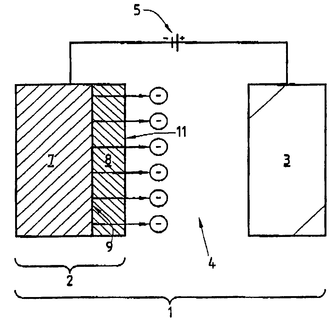
[0029]As can be seen in FIG. 1, the subject matter of the invention relates to a device 1 enabling electrons to be extracted in a vacuum, the device comprising an emission cathode 2 spaced apart from at least one anode 3 which in the example shown constitutes an anode for receiving electrons emitted by the cathode 2. The cathode 2 and the anode 3 define between them a volume 4 in which there is a vacuum (10−4 Torr to 10−8 Torr) or an ultrahigh vacuum (10−8 Torr to 10−12 Torr). The extraction device 1 also comprises a bias source 5 enabling the cathode 2 to be placed at a given potential relative to the anode 3. Practical implementation of the extraction device 1 is not described in greater detail below insofar as it is well known in the state of the art.

[0030]In accordance with the invention, the extraction device 1 comprises an emission cathode 2 having a first portion 7 forming an electron reservoir and constituted by at least one metal layer. The emission cathode 2 also has a sec...


PUM


Abstract

The method of the invention for extracting electrons in a vacuum consists in:making a cathode presenting at least one junction (9) between a metal (7) acting as an electron reservoir and an n-type semiconductor (8) possessing a surface potential barrier with a height of a few tenths of an electron volt, and presenting thickness lying in the range 1 nm to 20 nm;injecting electrons through the metal / semiconductor junction (9) to create a space charge in the semiconductor (8) sufficient to lower the surface potential barrier of the semiconductor to a value that is less than or equal to 1 eV relative to the Fermi level of the metal (7); andusing the bias source creating an electric field in the vacuum to control the height of the surface potential barrier (Vp) of the n-type semiconductor in order to control the emission of the electron flux towards the anode.

Description

TECHNICAL FIELD[0001]The present invention relates to the field of emitting electrons in a vacuum from a cathode in the broad sense.[0002]The subject matter of the invention thus covers the field of electron sources in the broad sense suitable for use in electronic devices or for making flat screens, in particular.PRIOR ART[0003]In conventional manner, an electron extractor device comprises an emission cathode and an anode spaced apart from each other with a vacuum or an ultrahigh vacuum existing between them. The anode and the cathode are interconnected by means of a bias source serving to place them at a given relative potential.[0004]In order to ensure that a constant flow of electrons is emitted into the vacuum from the cathode, it is necessary to extract the electrons from the potential in which they are trapped in the cathode material. Electrons can be extracted from the cathode by the technique of heating the cathode, so as to raise the energy of the electrons to a value whic...

Claims


Application Information

Patent Timeline
Patent Type & Authority Patents(United States)
IPC IPC(8): H01J1/30H01J9/02H01J1/308H01J29/04
CPCH01J1/308
Inventor VU THIEN, BINHDUPIN, JEAN-PIERRETHEVENARD, PAUL
Owner UNIV CLAUDE BERNARD LYON 1
Why Eureka
Try Eureka