
Amplifier with accurate built-in threshold

a technology of built-in thresholds and amplifiers, which is applied in the direction of pulse generators, pulse techniques, instruments, etc., can solve the problems of voltage detection errors, variance in the trip point of differential amplifiers, and limitations of certain physical parameters to limit and/or move the trip point of amplifiers

Inactive Publication Date: 2006-06-06
MICROCHIP TECH INC
View PDF10 Cites 41 Cited by
  • Summary
  • Abstract
  • Description
  • Claims
  • Application Information

AI Technical Summary

Benefits of technology

The patent describes a circuit that can detect changes in voltage levels and is immune to variations in temperature and transistor fabrication parameters. It uses a special transistor to generate a composite voltage that is proportional to the temperature and fabrication parameters. The circuit also includes a differential amplifier that is insensitive to changes in input offset voltage. This allows for accurate detection of voltage levels even in the face of changes in operating temperature and transistor fabrication parameters. The circuit can be used in various applications such as communication devices and sensors.

Problems solved by technology

In real world implementations, however, certain physical parameters limit and / or move the trip point of the amplifier.
Another factor that may cause variance in the trip point of a differential amplifier is the temperature at which it operates.
The same process and temperature variations can produce voltage detection errors on the order of 10% in these applications.

Method used


Image

  • Amplifier with accurate built-in threshold
  • Amplifier with accurate built-in threshold
  • Amplifier with accurate built-in threshold

Examples


Embodiment Construction

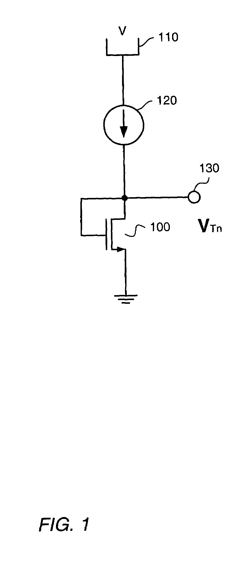
[0024]FIG. 1 shows a diagram of a prior art circuit for generating a voltage that approximates the threshold voltage of an NMOS transistor. The threshold voltage for an NMOS transistor may be defined as a voltage applied between the gate and source of the transistor that causes the free electron concentration at the gate oxide interface to be equal to the hole concentration in the bulk semiconductor material. In other terms, it is the lowest gate voltage for which appreciable current flows through the channel between the source and the drain.

[0025]The transistor threshold voltage may be dependent on a number of fabrication process parameters such as doping or implantation levels, and the dielectric constant and / or thickness of the gate insulating material. While many of these fabrication parameters may be fairly tightly controlled across transistors within a single die, significant variances may occur from die to die or from one wafer to another. This means that the threshold voltag...


PUM


Abstract

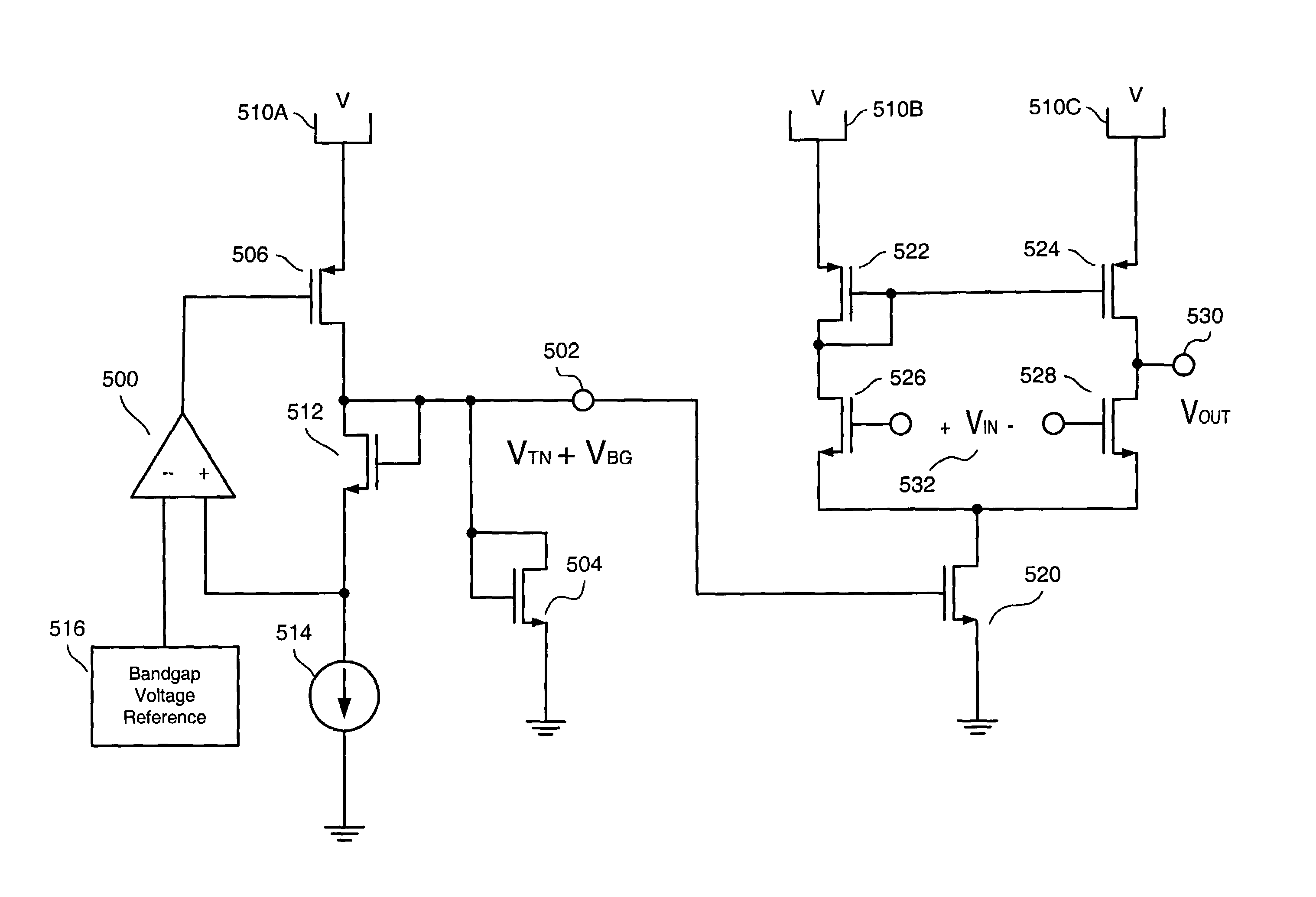
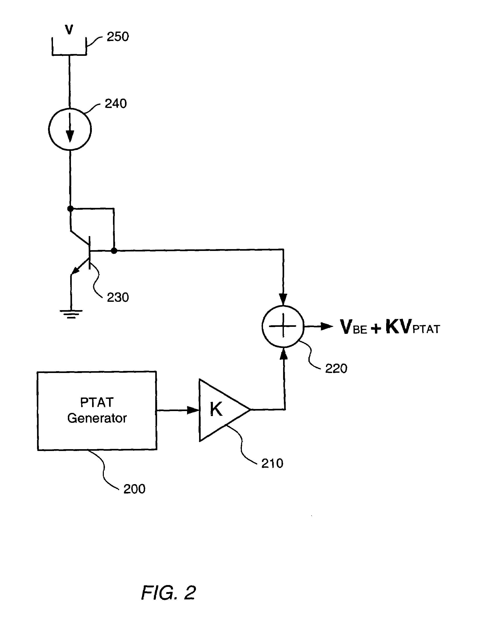
Various embodiments of a voltage level detector implemented as an integrated circuit whose trip point is approximately constant over variations in temperature as well as variations in transistor fabrication parameters are disclosed along with a differential amplifier whose input offset voltage is highly immune to said variations. In one embodiment, a voltage generator supplies a composite voltage to the gate of the tail current transistor of the voltage level detector or differential amplifier. The first component of the voltage is approximately equal to the threshold voltage of NMOS transistors comprised in the device over variations in operating temperature as well as variations in transistor fabrication parameters while the second component is approximately constant with respect to said variations. When applied to the gate of the tail current transistor, the first component may turn the transistor on in spite of the above-mentioned parametric variations.

Description

BACKGROUND OF THE INVENTION[0001]1. Field of the Invention[0002]This invention relates to integrated circuits, and more particularly, to differential amplifiers implemented as integrated circuits.[0003]2. Description of the Related Art[0004]Differential amplifiers are frequently employed to indicate when an input signal is greater than or equal to a certain value. The amplifier can be configured to change output states from one logic level to another when a voltage signal is applied between the positive and negative inputs of the amplifier. In this configuration the amplifier and associated circuitry are typically referred to as a voltage or level detector.[0005]The voltage level at which the detector will trip (change output states) is typically established by applying a constant reference voltage to the negative input of the amplifier and a variable signal to the positive input. The output of the detector will be at one state until the voltage at the positive input is greater than...

Claims


Application Information

Patent Timeline
Patent Type & Authority Patents(United States)
IPC IPC(8): G05F1/46G05F1/10
CPCG05F1/46
Inventor ILLEGEMS, PAUL F.
Owner MICROCHIP TECH INC
Learn More