
Insulating switching DC/DC converter

a dc/dc converter and switching technology, applied in the field of switching power supplies, can solve the problems of low efficiency of the overall apparatus, large loss of core components, and large number of components in the conventional circuit configuration, and achieve the effects of reducing the volume of the core, preventing dc bias magnetization, and reducing the dc bias magnetization of the cor

Active Publication Date: 2006-06-06
DENSO CORP
View PDF5 Cites 8 Cited by
  • Summary
  • Abstract
  • Description
  • Claims
  • Application Information

AI Technical Summary

Benefits of technology

[0022]Another aspect of the present invention has a primary circuit configured so that a connecting point of the series circuit of the clamp capacitor and the second switching device is changed in the primary circuit, and the series circuit of the clamp capacitor and the second switching device is connected across the terminals of the first switching device.
[0023]Additionally, in the circuit configuration of the present invention, it is also preferable to insert a capacitor in series with the primary coil (transformer primary winding) of the insulating transformer in order to prevent DC bias magnetization in the insulating transformer.
[0024]Still another aspect of the present invention is characterized in that in order to differentiate the input choke coil (primary choke winding) from the primary coil (transformer primary winding) of the insulating transformer beforehand, the coils are designed so as to have a difference in a degree of connection with the secondary coil of the transformer, so that the primary coil of the insulating transformer has a higher degree of connection and the input choke coil has a lower degree of connection.
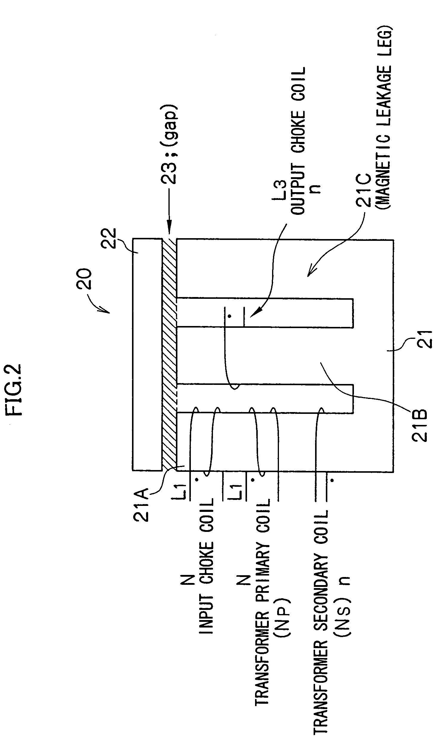
[0025]As described above, according to the first aspect of the present invention, the input choke coil and the output choke coil are integrated with the insulating transformer, the primary coil and the secondary coil of the transformer and the input / output choke coils are wound around the same core (magnetic core), and the coils are arranged in directions of canceling DC fluxes generated by the coils, so that the DC biased magnetization of the core is considerably reduced. Thus, it is possible to greatly miniaturize the volume of the core and reduce core losses as compared with the conventional art, thereby achieving a high-efficiency apparatus. Moreover, the circuit configuration can be realized by a single transformer. Hence, the number of components can be smaller than the double transform method.
[0026]Moreover, in order to attain the above objects, a second aspect of the present invention provides an insulating switching DC / DC converter, in which a DC voltage source is connected to the primary side of an insulating transformer, voltage is transformed by alternately turning on / off a first switching device and a second switching device so as not to simultaneously turn on the devices, the first and second devices being connected to the primary side, and the output of DC voltage is obtained via a secondary rectifier circuit of the insulating transformer, wherein an input choke coil, the primary coil of the insulating transformer, the secondary coil of the insulating transformer, and an output choke coil are wound around a common core, a primary circuit is formed on the primary side of the insulating transformer, the primary circuit including the first switching device connected in series with the primary coil, the input choke coil connected across the terminals of the primary coil, and a series circuit of a clamp capacitor and the second switching device which are connected across the terminals of the primary coil, and a secondary circuit is formed on the secondary side of the insulating transformer, the secondary circuit including a first rectifying device and a second rectifying device which are connected to the secondary coil, the output choke coil connected to the first and second rectifying devices, and an output smoothing capacitor connected to the output choke coil.
[0027]According to the present invention, in the DC / DC converter using an insulating transformer, the input choke coil and the output choke coil are integrated with the insulating transformer, the primary coil and the secondary coil of the transformer and the input / output choke coils are wound around the same core (magnetic core) to form a single component. In this way, the chokes and the transformer are formed into a single component and a converter circuit is realized by a single transformer. Thus, it is possible to reduce the number of components as compared with a conventional circuit.

Problems solved by technology

Although an output ripple voltage decreases, the core of magnetic components is considerably increased in total DC bias magnetization, the core has a large volume, core losses largely increase, and the overall apparatus has low efficiency.
Furthermore, the conventional circuit configuration requires a large number of components.

Method used


Image

  • Insulating switching DC/DC converter
  • Insulating switching DC/DC converter
  • Insulating switching DC/DC converter

Examples


Embodiment Construction

[0073]Preferred embodiments of the present invention will be described in detail in accordance with the accompanying drawings.

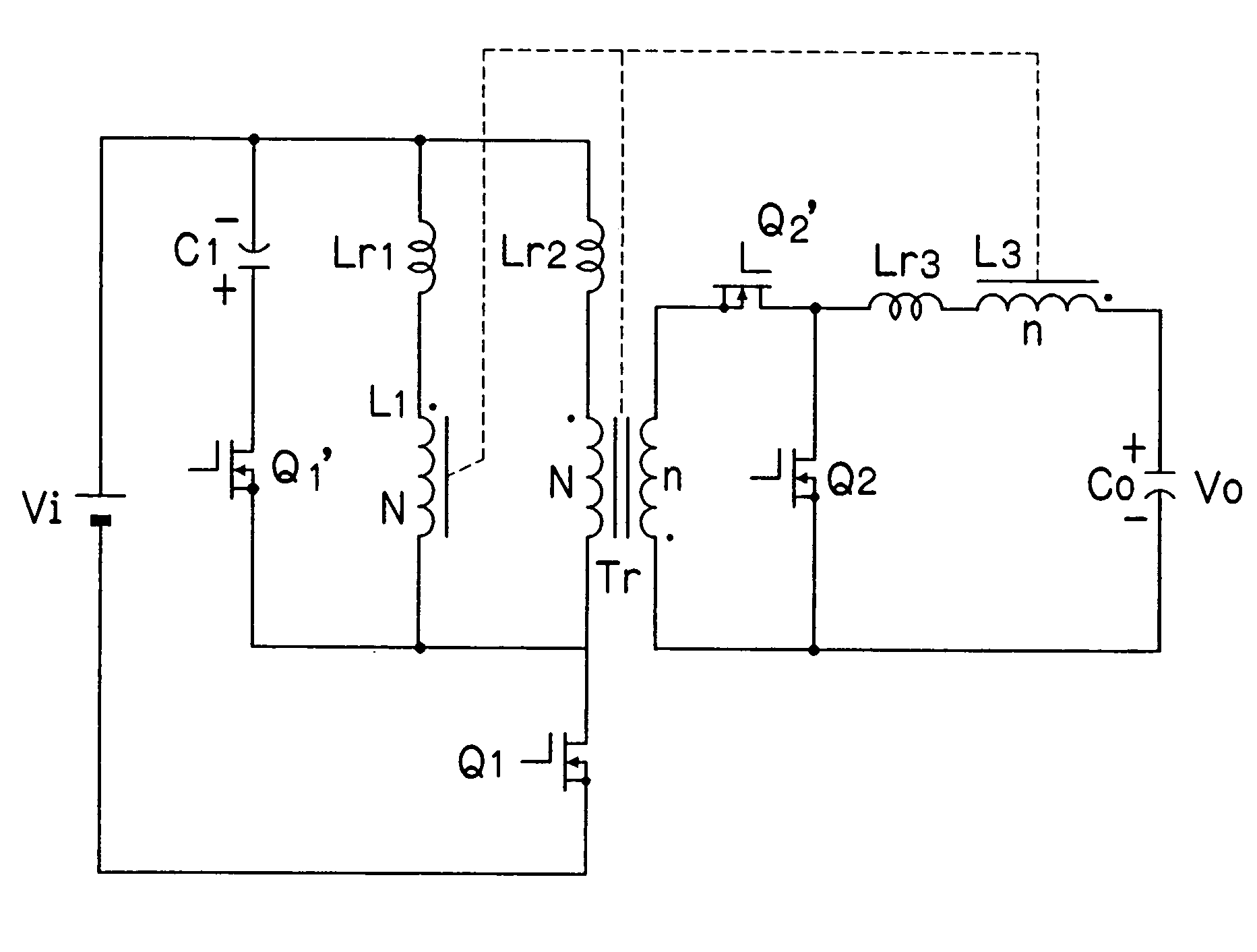
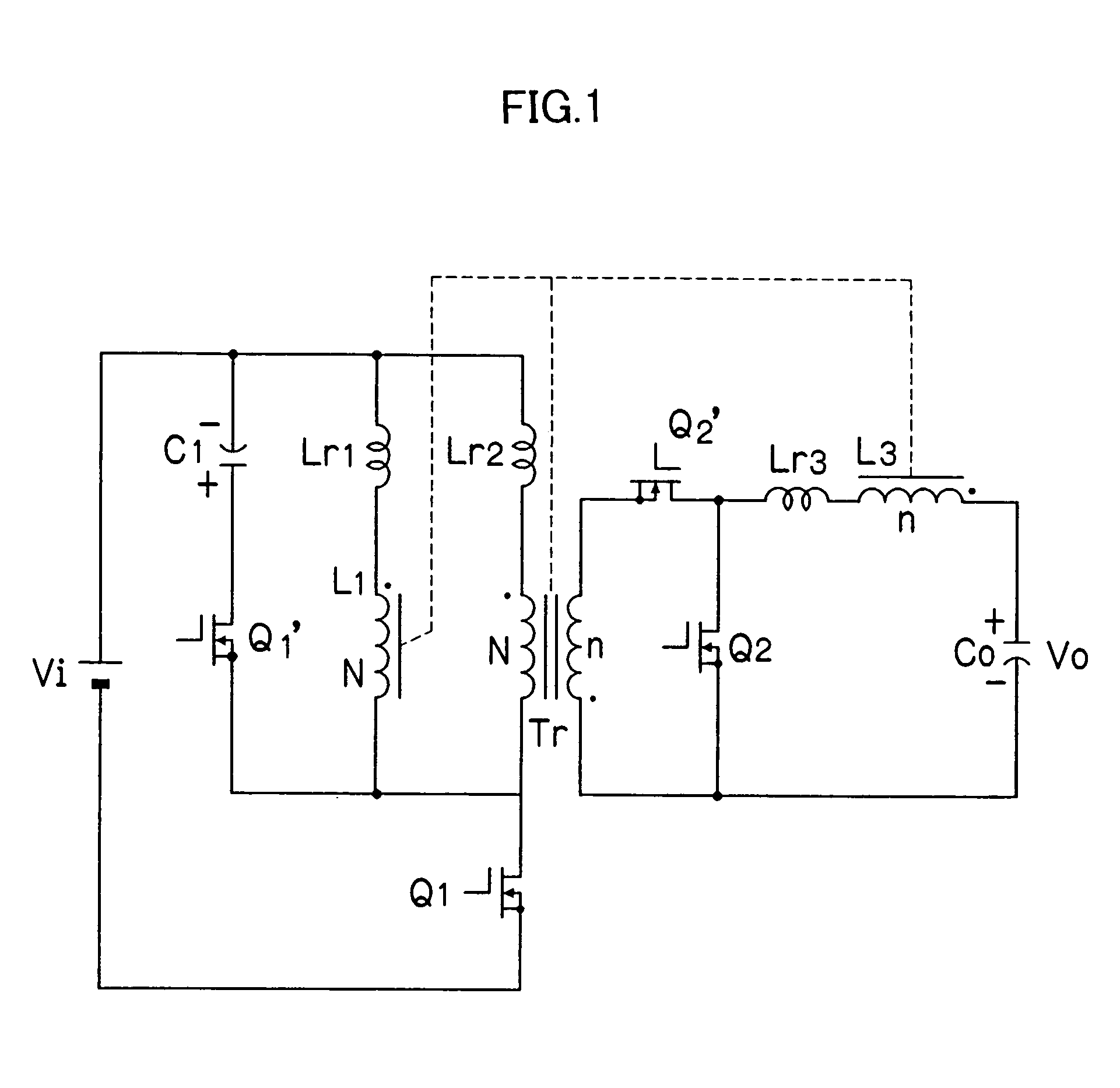
[0074]FIG. 1 is a circuit diagram showing a DC / DC converter (step-up active clamp forward converter). In FIG. 1, reference character Vi designates an input power supply, reference numeral C1 designates a clamp capacitor, reference numeral Q1′ designates a switching device using a FET, reference numeral Lr1 designates a leakage inductance, reference numeral L1 designates an input choke coil (N: the number of turns, N is a natural number), reference numeral Lr2 designates a leakage inductance, reference character Tr designates an insulating transformer (N: the number of turns of a primary coil, n: the number of turns of a secondary coil, n is a natural number), reference numeral Q1 designates a switching device using a FET, reference numerals Q2 and Q2′ designate switching devices acting as synchronous rectifying devices, reference numeral Lr3 designates a leak...


PUM


Abstract

In a switching DC / DC converter using an insulating transformer Tr, a primary coil and a secondary coil of the transformer Tr, an input choke coil L1, and an output choke coil L3 are wound around a common core and are formed into a single component. A primary circuit of the transformer Tr includes a switching device Q1 connected in series with the primary coil, an input choke coil L1 connected across the terminals of the primary coil, and a series circuit of a clamp capacitor C1 and a switching device Q1′ which are connected across the terminals of the primary coil. A secondary circuit of the transformer Tr includes rectifying switching devices Q2 and Q2′ connected to the secondary coil, the output choke coil L3, and an output smoothing capacitor C0. Further, a series circuit of the switching device Q1′ and the clamp capacitor C1 may be connected across the terminals of the switching device Q1. The coils are arranged in directions of canceling DC fluxes generated by the coils, so that it is possible to greatly reduce the DC bias magnetization of the core, the volume of the core, and core losses, thereby achieving higher efficiency in the overall apparatus.

Description

BACKGROUND OF THE INVENTION[0001]1. Field of the Invention[0002]The present invention relates to a switching power supply, and more particularly to a technique for higher efficiency and miniaturization of an insulating switching DC / DC converter and a technique for reducing the number of components.[0003]2. Description of the Related Art[0004]Conventionally switching power supply circuits which use partial resonant circuits to have zero-voltage switching are proposed (Reference 1, Reference 2). FIG. 31 shows an example of a conventional circuit structure. In FIG. 31, reference character Vi designates an input voltage source, reference numeral C1 designates a clamp circuit, and reference numeral Q1′ designates a switching device (e.g. MOSFET). Reference numeral Lr1 designates a leakage inductance which acts as an inductance for resonance. Reference numeral Tr1 designates a forward transformer (N: the number of turns of a primary coil, n: the number of turns of a secondary coil, N and ...

Claims


Application Information

Patent Timeline
Patent Type & Authority Patents(United States)
IPC IPC(8): H02M3/335
CPCH02M3/33569H02M2001/0064H02M1/0064H02M3/01
Inventor TAMURA, YOSHIMOTO
Owner DENSO CORP
Learn More