Distributed interactive multimedia system architecture

a multimedia system and multimedia technology, applied in the field of communication systems, can solve the problems of prohibitively expensive and unnecessary, limited multimedia for the most part, and most lans are susceptible to power loss

Inactive Publication Date: 2006-06-06
CISCO TECH INC
View PDF147 Cites 18 Cited by
  • Summary
  • Abstract
  • Description
  • Claims
  • Application Information

AI Technical Summary

Benefits of technology

[0061]Another aspect of the present invention provides a survivable communications network, comprising: (1) first and second manager subsystems, the first and second manager subsystems having first and second equivalent manager subsystem resources associated therewith, respectively, (2) first and second central hubs, each of the first and second central hubs having first and second equivalent central hub resources associated therewith, respectively, (3) a peripheral hub having peripheral hub resources associated therewith, (4) a common bus capable of coupling a selectable one of the first and second central hubs to a selectable one of the first and second manager subsystems, the first central hub thereby capable of decoupling from a failed one of the first and second manager subsystems and coupling instead to an operating one of the first and second manager subsystems, the second central hub thereby capable of decoupling from a failed one of the first and second manager subsystems and coupling instead to a functioning one of the first and second manager subsystems and (5) first and second redundant channels coupling

Problems solved by technology

To date, multimedia has, for the most part, been limited to stand-alone computer systems or computer systems linked together in a local area network (“LAN”).
The first of the fundamental integration issues is quality of service (“QoS”).
However, the delay itself is typically a function of video since it is the component requiring the most time for encoding and decoding.
These requirements are typical of private branch exchanges (“PBXs”) and other private network voice equipment, but are very atypical of Legacy LANs.
Most LANs are susceptible to power-losses, single points of failure and errant TE.
The second of the fundamental integration issues is network services.
While it is possible to construct a packet network with sufficient bandwidth, buffering and intelligence to accommodate synchronous traffic it is considered to be prohibitively expensive and unnecessary.
Furthermore, because it is deployed as a backbone, the aforementioned issues do not apply.
The third of the fundamental integration issues is interoperability.
Prior to 1992, this would have been almost impossible.
The specific design issue of concern is the systemic architecture and network design to implement a truly interactive network-wide multimedia system.
The concentration of system resources at a central location results in an increasingly complex network as network size increases.
However, slave-master-slave networks tend to be very complex to design, implement and maintain.
Furthermore, in systems employing

Method used


Image

  • Distributed interactive multimedia system architecture
  • Distributed interactive multimedia system architecture
  • Distributed interactive multimedia system architecture

Examples


Embodiment Construction

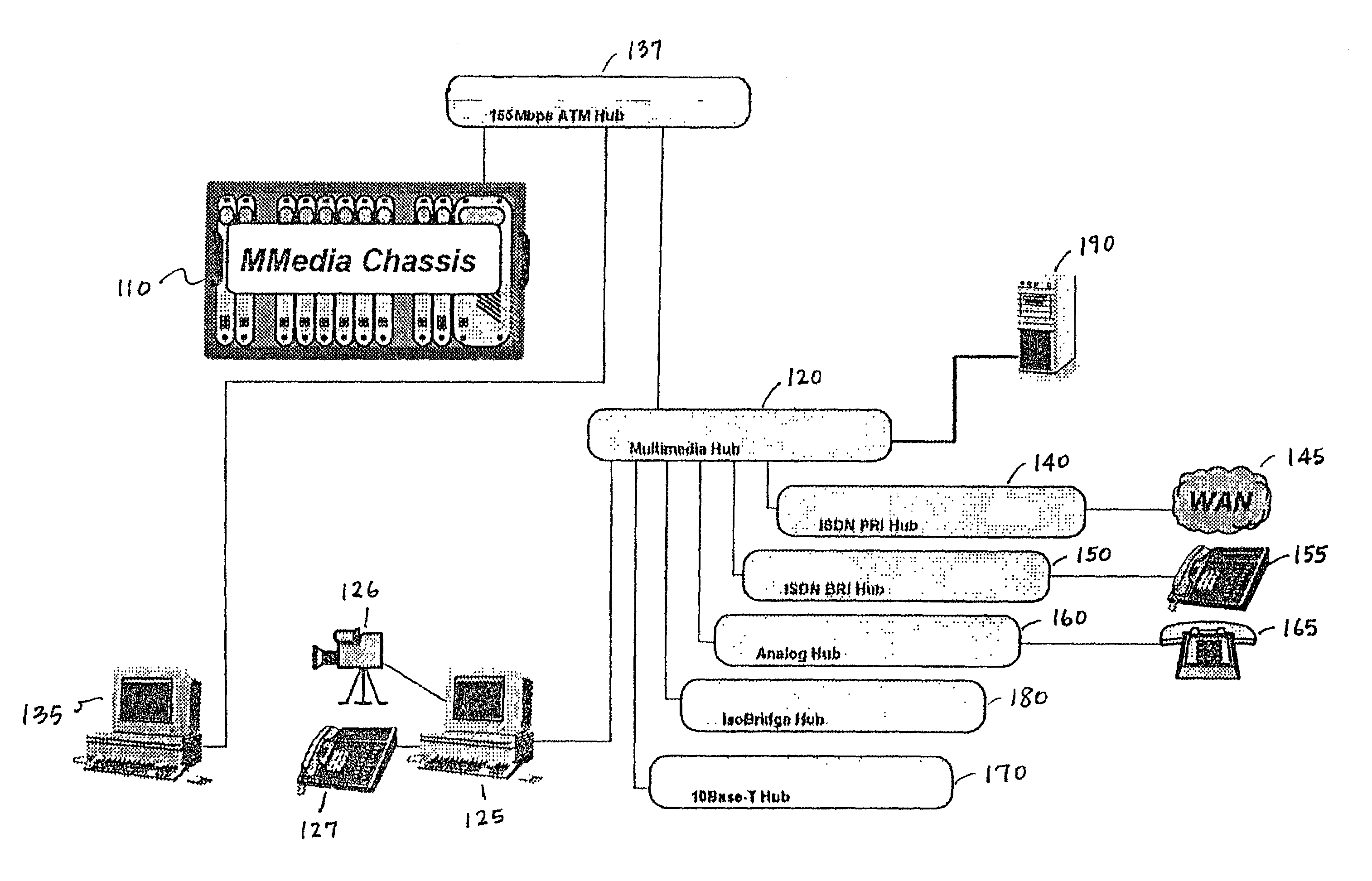
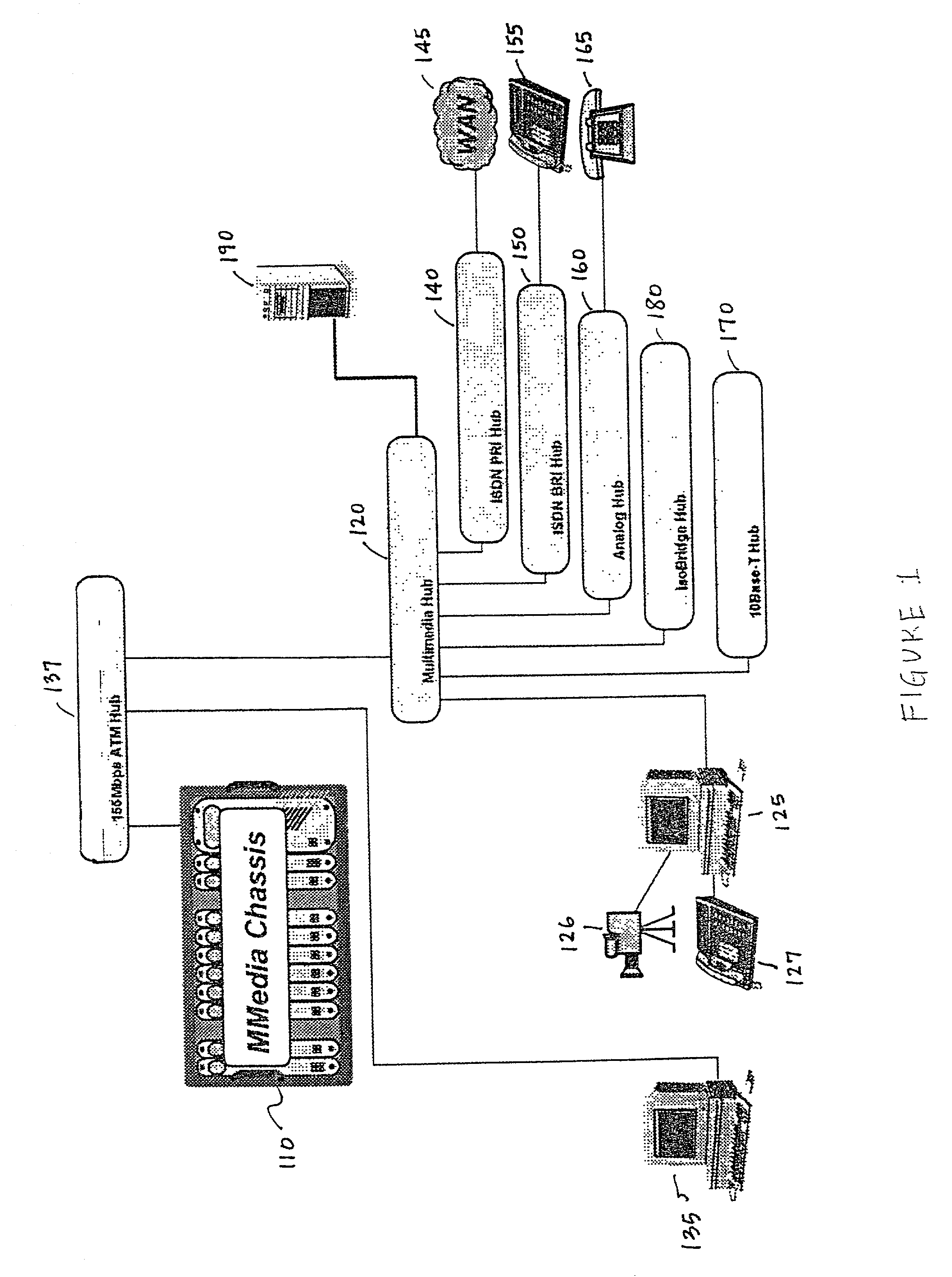
[0139]Referring initially to FIG. 1, illustrated is a system diagram of an interactive multimedia system according to the present invention.

[0140]The system, generally designated 100, may comprise a multimedia chassis 110 adapted to receive a plurality of cards therein. The system 100 may alternatively or additionally comprise a plurality of hubs in separate chassis. In the latter case, each of the hubs would contain one of the cards otherwise located in the multimedia chassis 110. Because the hubs are separate from each other, the following discussion will be directed to hubs, as opposed to cards, in the multimedia chassis 110, although it should be understood that the hubs can as easily exist as cards within the multimedia chassis 110.

[0141]A multimedia hub 120 forms a principal component of the system 100. In the illustrated embodiment, the multimedia hub 120 contains the following functions: 10Base-T hub repeater, B channel switch, isoEthernet® interfaces (allowing a subordinate...


PUM


Abstract

Various aspects of an interactive multimedia system and associated methods. In general, the multimedia system employs central and peripheral hubs that function to provide services to a plurality of clients of a call manager server, or manager subsystem. The hubs and subsystem cooperate to serve requests originating in the plurality of clients. The client-server-client architecture allows for distributed processing and resource management. Redundant connections between the various network subsystems and hubs provide survivability. Each subsystem or hub is provided with the ability to initialize or recover from systemic errors, thereby distributing initialization and recovery. Certain of the distributed resources are capable of being managed from other subsystems, thereby allowing sharing of the resources. An open numbering plan allows efficient call treatment of dialed numbers. Call processing is sharable between multiple manager subsystems. Finally, an iterative process is employed to ensure that calls routed through the network travel the shortest possible path.

Description

CROSS-REFERENCE TO RELATED APPLICATIONS[0001]This application is a continuation of U.S. application Ser. No. 09 / 164,503 filed Sep. 30, 1998 entitled “Distributed Interactive Multimedia System Architecture” now U.S. Pat. No. 6,304,576 issued Oct. 16, 2001, which is a continuation of U.S. application Ser. No. 08 / 402,834 filed Mar. 13, 1995 entitled “Distributed Interactive Multimedia System Architecture”, now U.S. Pat. No. 5,838,683 issued Nov. 17, 1998.TECHNICAL FIELD OF THE INVENTION[0002]The present invention is directed, in general, to communications systems and, more particularly, to a communications system employing a client-server-client architecture, allowing processing, storage and network resources to be distributed among subsystems and hubs of the network.BACKGROUND OF THE INVENTION[0003]Currently, “information superhighway” and “multimedia” are probably the most often spoken and least often understood aspects of a coming revolution in data communication. Although issues sp...

Claims


Application Information

Patent Timeline
IPC IPC(8): H04L12/28
CPCH04L29/06027H04L65/80H04L65/1069H04L65/1046H04L65/1101
Inventor CORLEY, ROBERT DAVIDDUNLAP, RICHARD A.HAHN, PAUL S.MCCLUNG, MICHAEL H.PEARCE, CHRISTOPHER E.PLATT, RICHARD B.
Owner CISCO TECH INC
Why Eureka
Try Eureka