Stimulation/sensing electrodes for use with implantable cardiac leads in coronary vein locations

a technology of electrodes and electrodes, which is applied in the direction of internal electrodes, electrical apparatus, therapy, etc., can solve the problems of inability to achieve optimal electrode-tissue orientation, unsatisfactory performance, and no electrode design is designed specifically for achieving optimal electrode-tissue orientation, etc., to enhance the electrical efficacy of the electrode and reduce the polarization

Inactive Publication Date: 2006-06-06
PACESETTER INC
View PDF15 Cites 16 Cited by
  • Summary
  • Abstract
  • Description
  • Claims
  • Application Information

AI Technical Summary

Benefits of technology

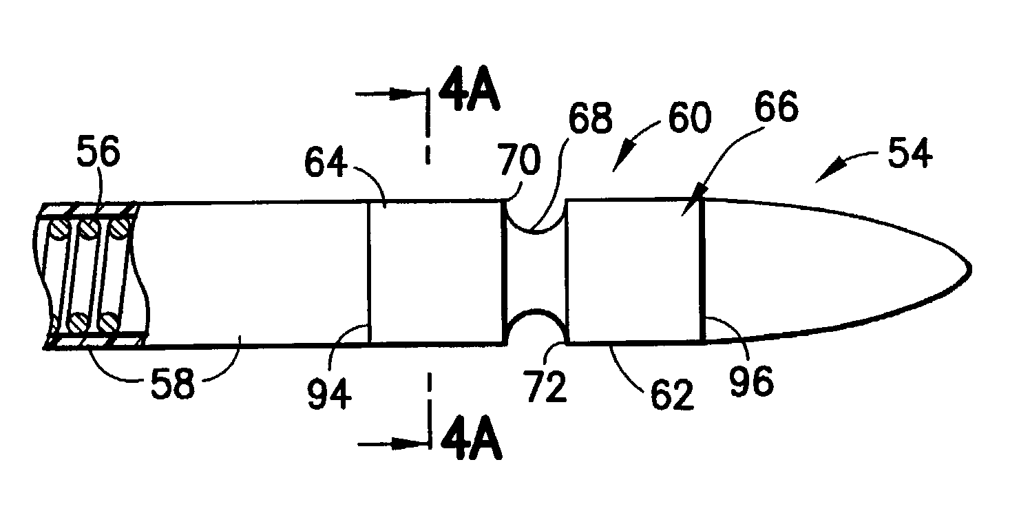
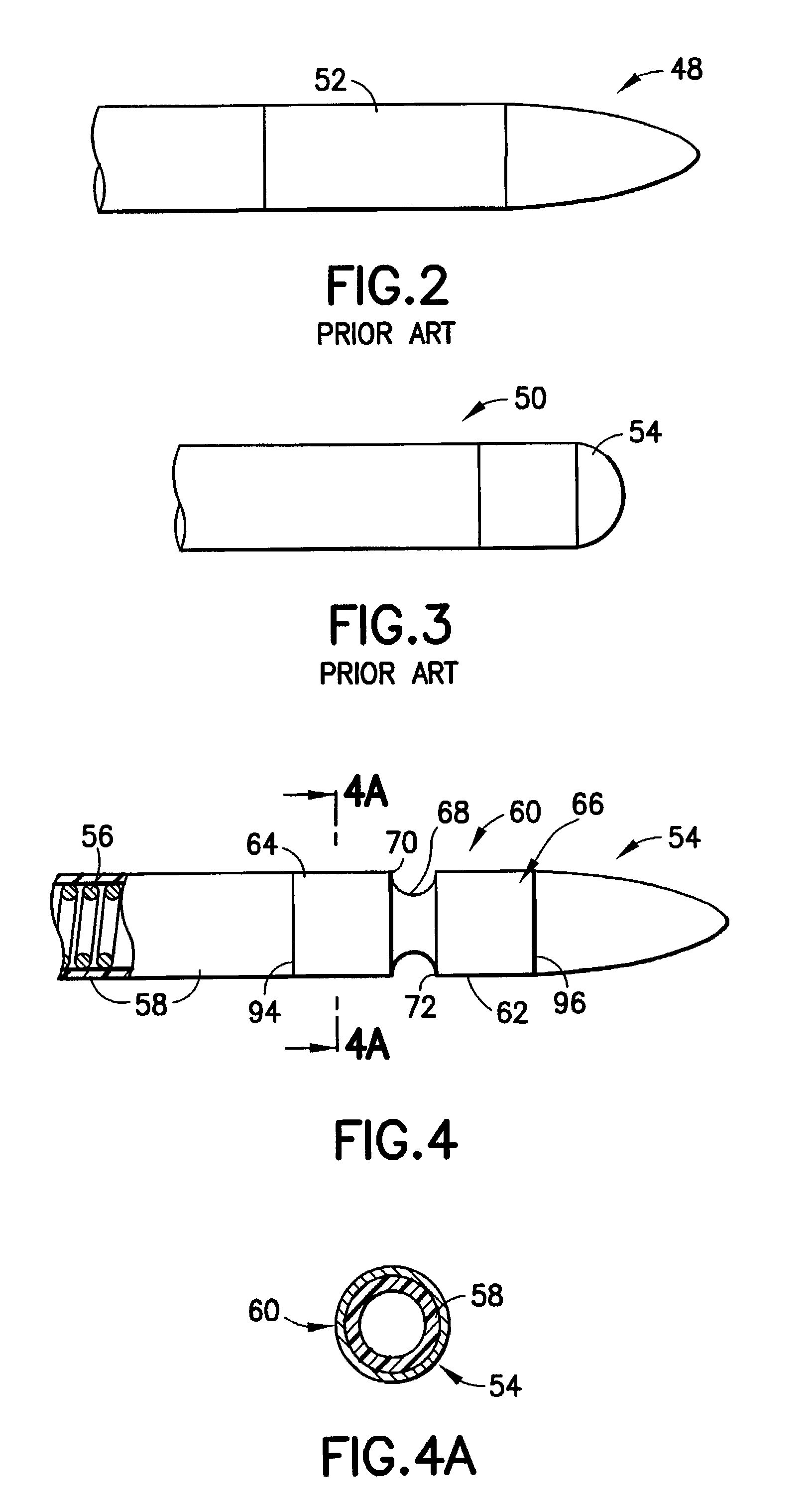
[0011]The present invention, then, relates to a lead assembly for a body implantable medical system adapted to transmit electrical signals between proximal and distal end portions of the lead assembly to thereby stimulate selected body tissue. The lead assembly of the invention includes an electrical conductor, an insulative sheath composed of silicone or polyurethane covering the conductor, an electrical connector coupled to the proximal end of the conductor for releasable attachment to a stimulating pulse generator and a distal electrode coupled to the distal end of the conductor. The distal electrode has an outer surface generally coaxial with the lead assembly, and faces transversely of the longitudinal axis of the lead assembly, and generally lies parallel to the selected body tissue intended for stimulation. The outer surface of the distal electrode is composed of a biocompatible metallic alloy and includes a layer of a material that exhibits low polarization and thereby enhances the electrical efficacy of the electrode.
[0012]It has been found that at locations of the distal electrode at which discontinuities occur, such as an interface between the electrode and the insulation sheath, or at corners or edges demarking the interface between adjacent transverse surfaces of the electrode, a concentration of the electrical charge occurs which creates a concentrated electrical field and substantially improves the effectiveness of the stimulation directed to the selected body tissue.
[0016]Another feature of the present invention is the provision of such optimal stimulating electrode designs which provide significantly improved electrical field distribution directed towards excitable cardiac tissue in a coronary vein.
[0017]Still another feature of the present invention is the provision of such a stimulating electrode which effectively reduces the losses of electrical current occurring in the blood stream.
[0018]Yet another feature of the present invention is the provision of such a stimulating electrode which provides enhanced stability of the electrode at the tissue stimulation site.
[0019]Still a further feature of the present invention is the provision of such a stimulating electrode for use with an associated lead assembly having low polarization which results in lower capture thresholds, increased sensing thresholds, and clearer evoked response signals.

Problems solved by technology

Typically, implantation within the right atrium and the right ventricle has been preferred to implanting leads within the left atrium and the left ventricle, which has generally been thought to be too invasive of a procedure and to pose undesirable risks of complications to the flow of blood in the circulatory system.
However, as the blood in the circulatory system is so primarily pumped by the left atrium and the left ventricle, pacing the right atrium and the right ventricle may not always provide optimum results in ensuring adequate cardiac activation and hemodynamics.
However, none of these electrode designs are designed specifically for achieving optimal electrode-tissue orientation to achieve (in turn) optimal cardiac stimulation thresholds in the coronary veins.
They are not able to perform optimally as the electrodes for these leads are not able to provide electrical fields that are optimally directed towards excitable cardiac tissue.
This after-potential prevents the accurate sensing of intrinsic cardiac electrical activity.
However, the increase in interface capacitance, in turn, lowers the polarization artifact typically seen following the pacing pulse.

Method used


Image

  • Stimulation/sensing electrodes for use with implantable cardiac leads in coronary vein locations
  • Stimulation/sensing electrodes for use with implantable cardiac leads in coronary vein locations
  • Stimulation/sensing electrodes for use with implantable cardiac leads in coronary vein locations

Examples


Embodiment Construction

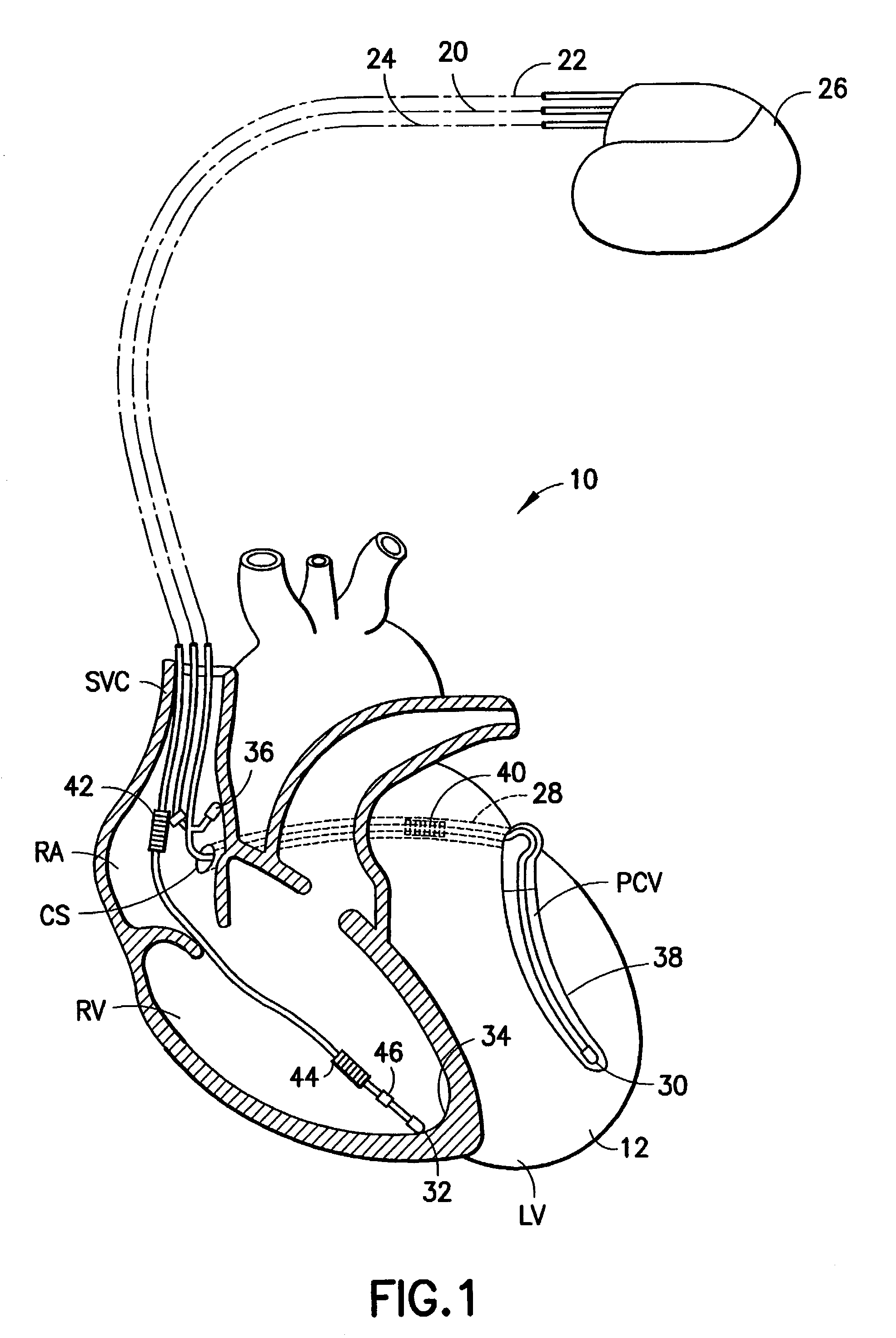
[0049]Refer now to the drawings and, initially, to FIG. 1 in which is shown a diagrammatic perspective view of an implanted system 10 for providing electrical stimulation of a heart 12 incorporating features of the present invention. Although the present invention will be described with reference to the embodiments shown in the drawings, it should be understood that the present invention can be embodied in many alternate forms or embodiments. In addition, any suitable size, shape or type of elements or materials consistent with, and suitable for, the invention could be used.

[0050]In FIG. 1, there are also illustrated implantable leads 20, 22, 24 generally embodying the invention for stimulation of the body, the heart 12 in this instance, by means of a pacemaker 26 or other suitable pulse generating device. This is a cross-section view of a human heart showing the right atrium (RA) and the right ventricle (RV) along with the coronary sinus CS and a vein 28 of the left side of the hea...


PUM


Abstract

A lead assembly for a body implantable medical system adapted to transmit electrical signals between proximal and distal end portions of the lead assembly to thereby stimulate selected body tissue includes an electrical conductor, an insulative sheath composed of silicone or polyurethane covering the conductor, an electrical connector coupled to the proximal end of the conductor for releasable attachment to a stimulating pulse generator and a distal electrode coupled to the distal end of the conductor. The distal electrode has an outer surface generally coaxial with the lead assembly and facing transversely of the longitudinal axis of the lead assembly and generally parallel to the selected body tissue intended for stimulation. The outer surface of the distal electrode is composed of a biocompatible metallic alloy and includes a layer of a material that exhibits low polarization and thereby enhances the electrical efficacy of the electrode.

Description

FIELD OF THE INVENTION[0001]The present invention relates generally to lead assemblies for connecting implantable medical devices with selected body tissue to be stimulated by such devices, and more particularly to stimulating electrodes for use with such lead assemblies designed to provide optimized stimulation of the body tissue.BACKGROUND OF THE INVENTION[0002]Implantable cardiac devices are commonly used for treating patients with heart arrhythmias. These devices include well-known pacemakers and implantable cardioverter defibrillators (ICD's). In general, these devices include a lead that is adapted to be implanted in the body of the patient so as to be positioned adjacent the heart and a control unit that is also adapted to be implanted within the patient which is connected to the lead so as to deliver electrical impulses to the heart via the lead. Pacemaker devices can be very sophisticated and include sensors and processing capabilities so that pacing is provided only when n...

Claims


Application Information

Patent Timeline
Patent Type & Authority Patents(United States)
IPC IPC(8): A61N1/05
CPCA61N1/0565
Inventor CHITRE, YOUGANDHHELLAND, JOHN R.
Owner PACESETTER INC
Why Eureka
Try Eureka