
Motor driven sampling apparatus for material collection

a sampling apparatus and motor drive technology, applied in the direction of sampling, instruments, measurement devices, etc., can solve the problems of increasing fatigue, affecting the quality of blood samples, and the ability to extract dried blood samples quickly, so as to eliminate slippage

Inactive Publication Date: 2006-06-13
GE HEALTHCARE BIO SCI CORP
View PDF11 Cites 11 Cited by
  • Summary
  • Abstract
  • Description
  • Claims
  • Application Information

AI Technical Summary

Benefits of technology

The device effectively reduces repetitive stress injuries, minimizes cross-contamination by eliminating artifact fibers, and allows for high-throughput sampling of various materials with increased versatility and accuracy, while maintaining ergonomic comfort.

Problems solved by technology

However, there are several limitations which make these devices a less than desirable tool for extracting dried blood samples from blood cards.
Due to the tension of the spring this operation can create fatigue in the finger, hand and wrist muscles after only a few sample punches are produced, and increase in fatigue over a lengthier period of repetitive punching.
Therefore repetitive stress injury may develop quickly with this type of punch where even the smallest sampling pools to be collected become an arduous and painful task.
While the punch and die on this unit remain open at all times allowing for quick insertion of source material for sampling, the vertical height of the throat between the punch and die on these punches may not be large enough to handle some blood cards of greater thickness, or versatile to sample other materials soft enough to be sampled with this instrument but too thick to be inserted.
Another problem with these punches is that the horizontal length of the throat is limited and therefore may restrict sampling over all surface areas and locations of a particular blood card.
Sampling directly from the center of the card is not possible with a conventional paper punch because the horizontal throat of the punch is less than the distance from the edge of the card to the center of the card.
Therefore this type of punch is limited to sampling blood cards with surface dimensions that ensures the card can be inserted to allow the punch to reach any location on the surface where the blood may have collected.
If the die and surrounding area on the punch is left uncleaned or uncleared between samples, then these artifacts may build up and result in carry over to the next blood card and subsequently be deposited with the next sample into the extraction vial.
Therefore this type of punching device lends itself to cross contamination.
These types of punches are restricted in their application to primarily sampling blood cards and cannot suitably sample gels, tissue or other soft substrates.
Because plants have a liquid component in the leaves, repeated sampling allows for a build up of plant saps which cause samples to adhere to the punch and are not easily transferred through the die.
However, since there is no punch and die mechanism the sample must rest on a pliable support.
However, the Uni-Core is still not suited for high throughput as repetitive stress injury will develop with prolonged use.
Both the paper punch and Harris Uni-Core are manual punches and are not designed to punch or core a sample directly into a collection vial, however, the paper punch can accomplish this but not with consistent speed and repetition.
However, delivery of sample is not visible to the operator and therefore cannot be confirmed after each operation.
Again a punch and die mechanism is used and this can create artifacts and lead to cross contamination.
This system is also restricted to sampling 96-spot blood cards and only samples with thicknesses equivalent to blood cards.
These former examples of prior art, while functional, are not suited for high throughput sampling regimes, and, with the exception of the Harris Uni-Core, may only be used with blood cards of a limited surface area and thickness.
These systems are only designed to sample blood cards and no other source material.
There are no hopper feeding systems for automated feeding of cards, and therefore each card must be inserted manually.
This may create a safety issue as one or both hands may be used and therefore places the operators fingers in the vicinity of the punch.
If the operation is not synchronized, the pedal or platen activation may result in operator injury.
This may result in fibers becoming entangled with samples due to static build up and may lead to cross contamination.
These systems offer increased throughput but may not offer the expected confidence that the samples generated are always delivered where expected nor that there is no cross contamination occurring between subsequent samplings.
Contamination becomes a chronic condition of these sampling tools which is not always easy to monitor nor are the systems designed to monitor the creation and dispersion of such artifacts.
The sample may now be directed into a well or vial and the operator can visually confirm delivery, which is not possible on the prior art automated punching systems.
The tips are disposable and can be easily replaced which is not possible with the prior art manual or automated punching systems.
There are disadvantages with the prior art coring tools, most notably the susceptibility of the operator to Repetitive Stress Injury (RSI) and more specifically Carpal Tunnel Syndrome (CTS), a condition which interferes with the use of the hand and is caused when too much pressure is put on the nerve that runs through the wrist.
Even minimal use of the manual coring device over short periods of time has lead to reported wrist discomfort.
This discomfort is acerbated when the manual coring device is used in high throughput sampling environments requiring extended daily use by a single operator.
When used in high throughput sampling regimes this can, and does, lead to repetitive stress injury (RSI).
A search did not disclose any prior art electric coring tools for sample collecting.

Method used


Image

  • Motor driven sampling apparatus for material collection
  • Motor driven sampling apparatus for material collection
  • Motor driven sampling apparatus for material collection

Examples


Embodiment Construction

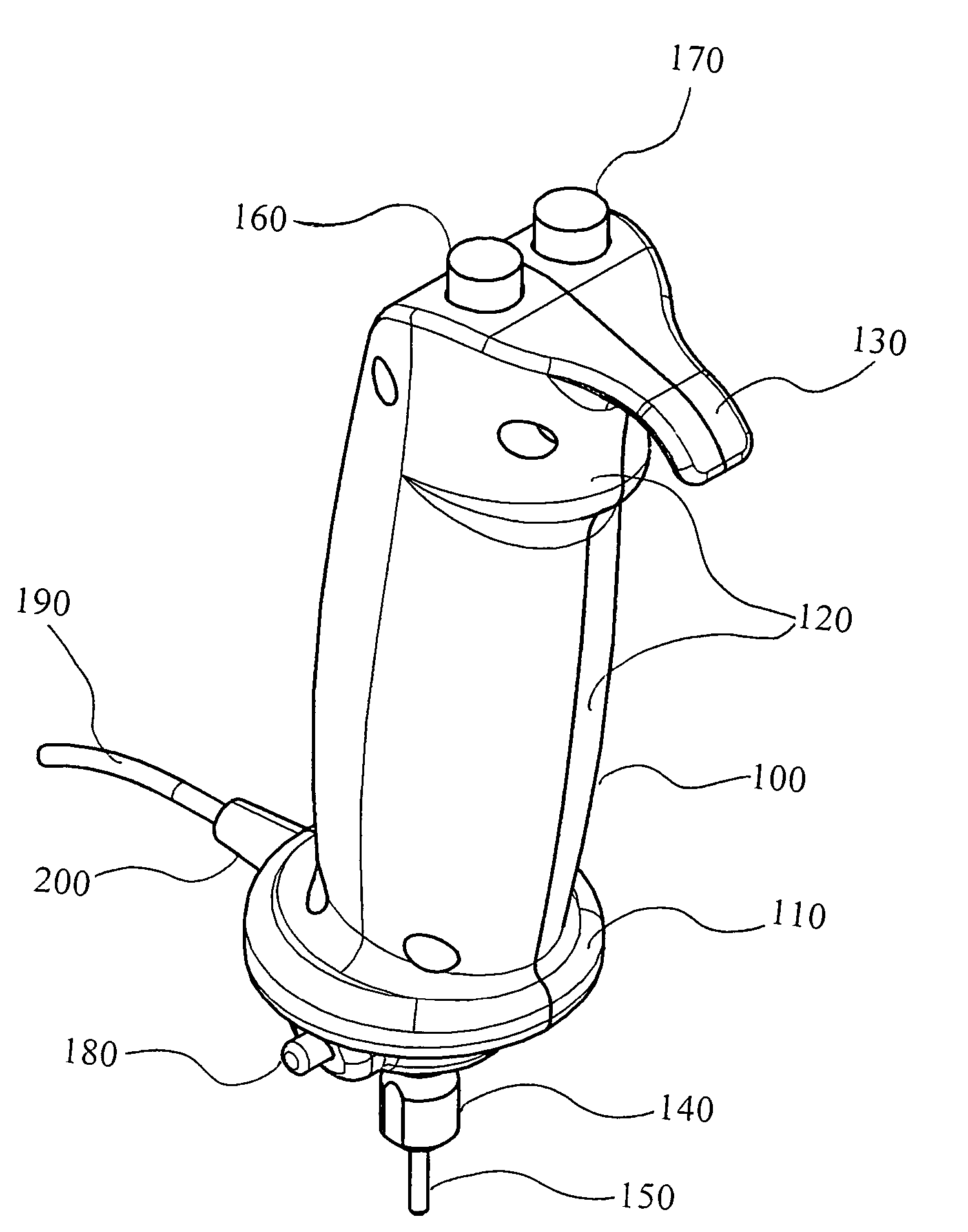
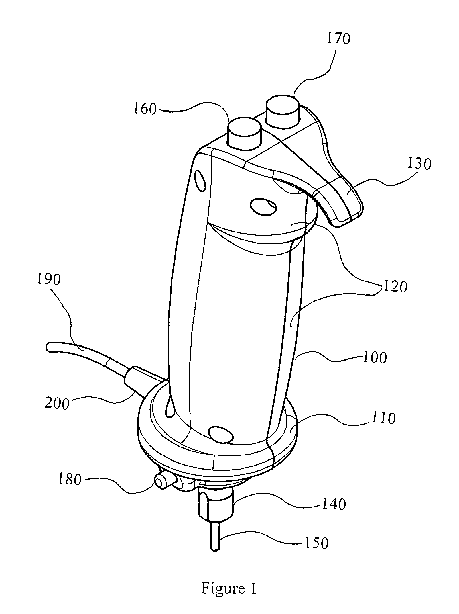
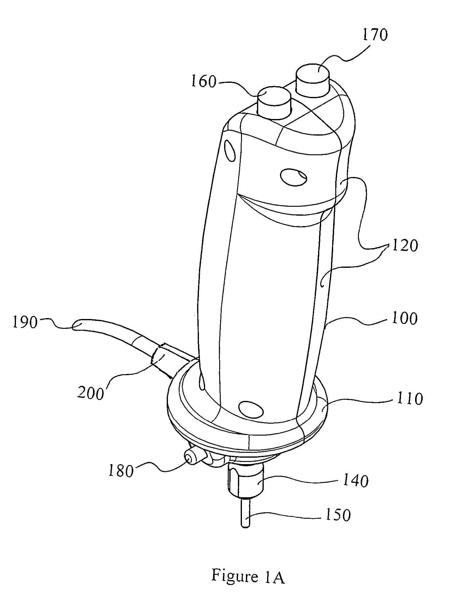
[0076]Referring to FIG. 1, a preferred embodiment of a sample collection device constructed in accordance with the principles of the invention is shown. A handle feature 100 blends to a horizontal flange feature 110 at the bottom as a hollow clamshell casing. A collet nut 140 at the lower end below the flange 110 holds the sample sleeve 150. To facilitate ease of holding the unit, finger contours 120 are included on the front of the casing. To reduce slipping of the hollow clamshell handle 100 through the hand a curved extension shaped as a hook 130 has also been added as a blended feature above the finger contours 120. The motor actuation button 160 and the ejection button 170 are positioned at the top of the hollow clamshell casing 100. The spindle lock button 180 extends just below the base of flange 110. The power supply cord 190 extends from a cord strain release 200 which extends from the rim of the flange 110.

[0077]FIG. 1A repeats the embodiments described for FIG. 1 but does...


PUM

PropertyMeasurementUnit
diametersaaaaaaaaaa
rotationaaaaaaaaaa
pressureaaaaaaaaaa

Abstract

A motorized sample collection apparatus having a hollow clamshell casing with a contoured grip for the fingers, a horizontal extension to eliminate slippage when held in a user's hand, and a flange bottom portion from which a sample sleeve extends downwards. Within the clamshell casing an electric motor is mounted which drives, via spur gears the sample sleeve in a rotational manner. The distal end of the sample sleeve, is a cutting edge circumscribing a circular region. An ejection rod slides reciprocally within the sample sleeve between a retracted stowed position and an expulsion position. User cuts a sample from a substrate by engaging contact between the cutting edge of the sample sleeve and the substrate, applying pressure against the substrate and activating the motor to rotate the sample sleeve. Activation of the ejection rod towards the expulsion position displaces the sample into an appropriate collecting vessel.

Description

BACKGROUND OF THE INVENTION[0001]1. Field of Invention[0002]Micro-sampling devices are conventionally used to slice / cut, scoop, punch or bore samples from source materials such as paper, cloth, wood, gels, human and animal tissues and the like. The samples collected may undergo wet chemical treatment; may be examined microscopically, used to create tissue micro-array slides, or be further chemically analyzed by a variety of analytical equipment including pyrolysis gas chromatographs, mass spectrometers, scanning electron microscopes and Fourier infrared spectrometers.[0003]A widely available and commonly used micro-sampling tool is the garden variety paper punch. These tools are manually operated and available a craft stores or business supply outlets. They have been routinely used to sample dried blood stored on blood cards or for sampling leaves in the study of crop genetic events. There are also dedicated, electric, automated punches, with large footprints designed for high throu...

Claims


Application Information

Patent Timeline
Patent Type & Authority Patents(United States)
IPC IPC(8): G01N1/08
CPCG01N1/08
Inventor HARRIS, JOEL STEVEN
Owner GE HEALTHCARE BIO SCI CORP
Learn More