Digital phase detector

a digital phase detector and phase detector technology, applied in the field of signal generation, can solve the problem of direct reduction of the open loop gain of the phase-locked loop

Active Publication Date: 2006-06-13
TERADYNE
View PDF2 Cites 32 Cited by
  • Summary
  • Abstract
  • Description
  • Claims
  • Application Information

AI Technical Summary

Problems solved by technology

Another problematic aspect of the conventional architecture 100 is that the divider 218 of the phase-locked loop 200 directly reduces the phase-locked loop's open loop gain.

Method used


Image

  • Digital phase detector
  • Digital phase detector
  • Digital phase detector

Examples


Embodiment Construction

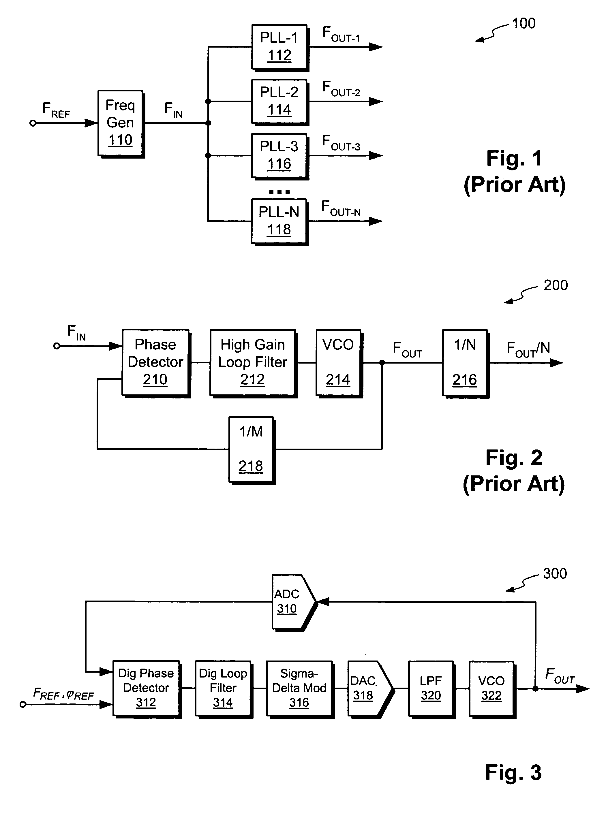
[0027]FIG. 3 shows an illustrative embodiment of a frequency synthesizer 300 according to the invention. The synthesizer 300 has an input for receiving input data indicative of a frequency and phase (FREF, ΦREF). The synthesizer 300 has an output for generating an output signal FOUT. The frequency and phase of FOUT are determined by the input data.

[0028]In the illustrative embodiment of FIG. 3, the synthesizer 300 is a feedback circuit having a forward path and a feedback path. The forward path includes a digital phase detector 312, a digital loop filter 314, a sigma-delta modulator 316, a DAC (digital-to-analog converter) 318, an analog filter 320, and a VCO (voltage-controlled oscillator) 322. The feedback path includes an ADC (analog-to-digital converter) 310.

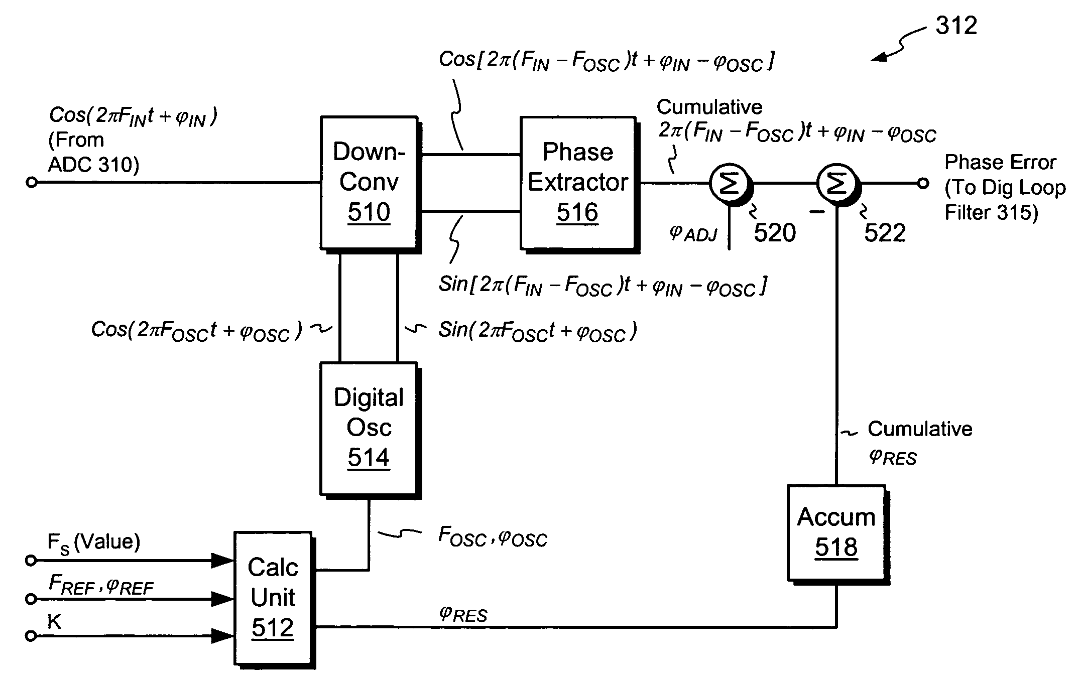
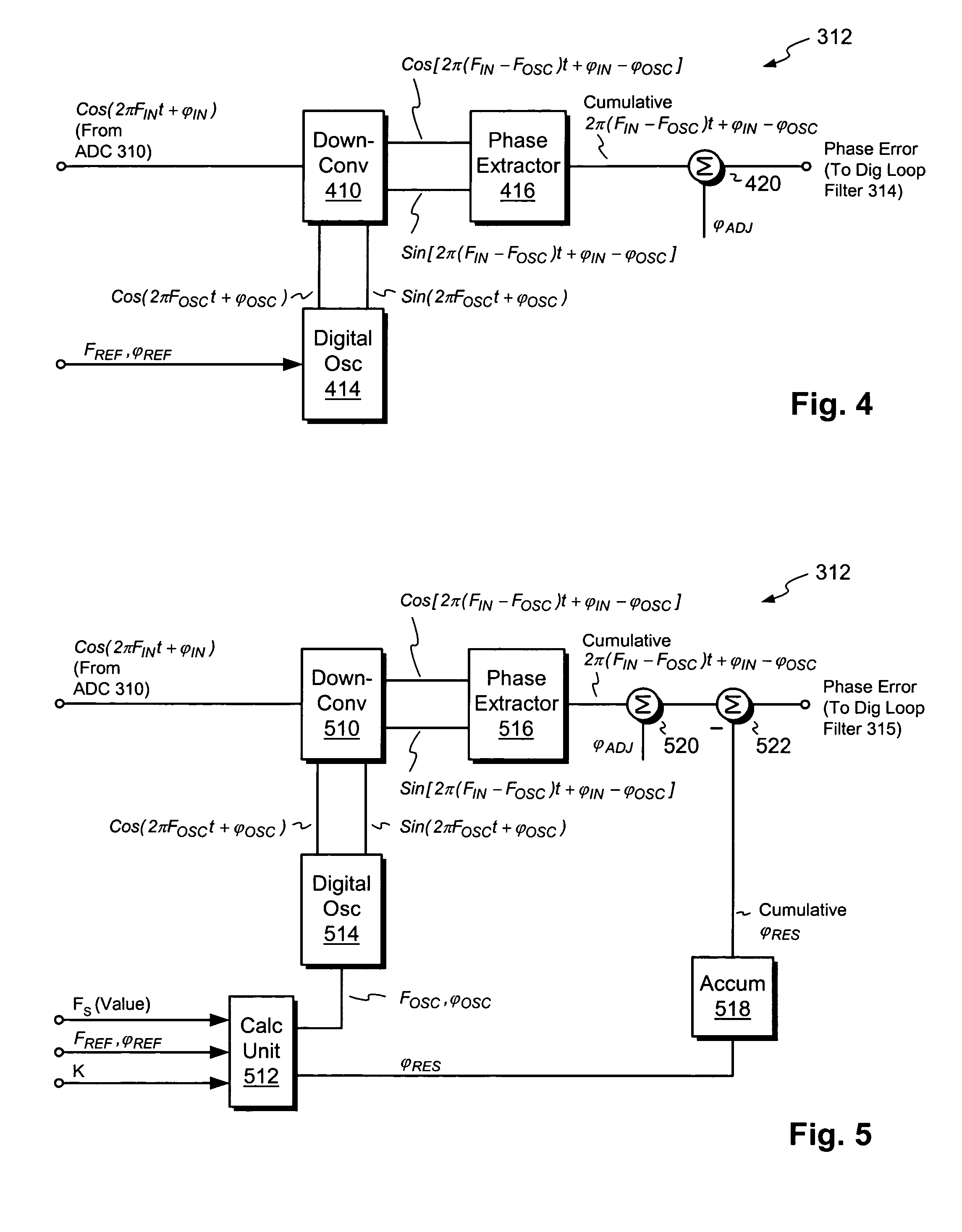
[0029]The digital phase detector 312 has a first input for receiving the input data (FREF, φREF) and a second input for receiving a digital feedback signal. The digital phase detector 312 preferably generates a reference fre...


PUM


Abstract

A high performance phase detector includes a local digital oscillator for generating a digital reference signal of programmable frequency and phase. The phase detector accumulates a difference in phase between the digital reference signal and a sampled input signal to produce a measure of phase error. The phase detector can be advantageously used in a frequency synthesizer to produce signals with low phase noise and accurate phase control. Synthesizers of this type can further be used to as building blocks in ATE systems and other electronic systems for generating low jitter clocks and waveforms.

Description

CROSS-REFERENCES TO RELATED APPLICATIONS[0001]Not Applicable.STATEMENT REGARDING FEDERALLY SPONSORED RESEARCH OR DEVELOPMENT[0002]Not Applicable.REFERENCE TO MICROFICHE APPENDIX[0003]Not Applicable.BACKGROUND OF THE INVENTION[0004]1. Field of the Invention[0005]This invention relates generally to signal generation and more specifically to the synthesis of periodic signals with high signal integrity.[0006]2. Description of the Related Art[0007]Automatic test equipment (ATE) and other high performance electronic systems rely upon the ability to generate precise periodic signals. ATE requires these signals for testing state-of-the-art electronic devices, such as computer chips, telecommunications chips, and electronic assemblies. As these devices and assemblies become more advanced, ATE must commensurately advance to maintain high testing standards.[0008]FIG. 1 shows a conventional architecture 100 used by many ATE systems for synthesizing precise periodic signals. The architecture 100...

Claims


Application Information

Patent Timeline
Patent Type & Authority Patents(United States)
IPC IPC(8): G01R29/00H03L7/085G01R25/00G01R25/04G01R31/28G01R31/317G01R31/319H03D3/00H03D13/00H03L7/00H03L7/087H03L7/091H03L7/16
CPCG01R25/04G01R31/31709G01R31/31922H03L7/16H03L7/085H03L7/091H03D13/003H03L7/087
Inventor XU, FANG
Owner TERADYNE
Why Eureka
Try Eureka