Remote control system for on-vehicle equipment and remote control method for the same

a technology of remote control system and on-vehicle equipment, which is applied in the direction of process control, machine control, program control, etc., can solve the problems of inability to secure the communication area between the on-vehicle unit and the portable unit, the inability to lock or unlock the door or re-start the internal combustion engine, and the inability to secure the communication area. , to achieve the effect of suppressing the incidence of communication errors and stable communication area

Active Publication Date: 2006-06-13
TOYOTA JIDOSHA KK
View PDF18 Cites 29 Cited by
  • Summary
  • Abstract
  • Description
  • Claims
  • Application Information

AI Technical Summary

Benefits of technology

[0015]According to this on-vehicle equipment remote control system and remote control method for the same, the on-vehicle unit transmits the request signal on the second frequency after the start of the vehicle power source. The second frequency is higher than the first frequency that is transmitted prior to the vehicle power source start. In this configuration, it is difficult for noise generated by the operation of the vehicle power source to superimpose over the request signal, in com

Problems solved by technology

If the internal combustion engine is started in this way without inserting the ignition key into the cylinder, however, there is the possibility that the portable unit may be taken away from the vehicle while the internal combustion engine is operating.
If the portable unit is taken away from the vehicle and the vehicle continues operating in that state, a problem is caused whereby locking or unlocking of the door or re-starting the internal combustion engine will become impossible once the internal combustion engine has then stopped operating.
However, if the high frequency radio wave is utilized for the downlink communication, a stable communication area between the on-vehicle unit and the portable unit cannot be secured, and a situation arises where highly efficient and secure communication between the two units cannot take place.
When the internal combustion engine that powers the vehicle or an inverter of an electric vehicle or the like is operating, how

Method used


Image

  • Remote control system for on-vehicle equipment and remote control method for the same
  • Remote control system for on-vehicle equipment and remote control method for the same
  • Remote control system for on-vehicle equipment and remote control method for the same

Examples


first embodiment

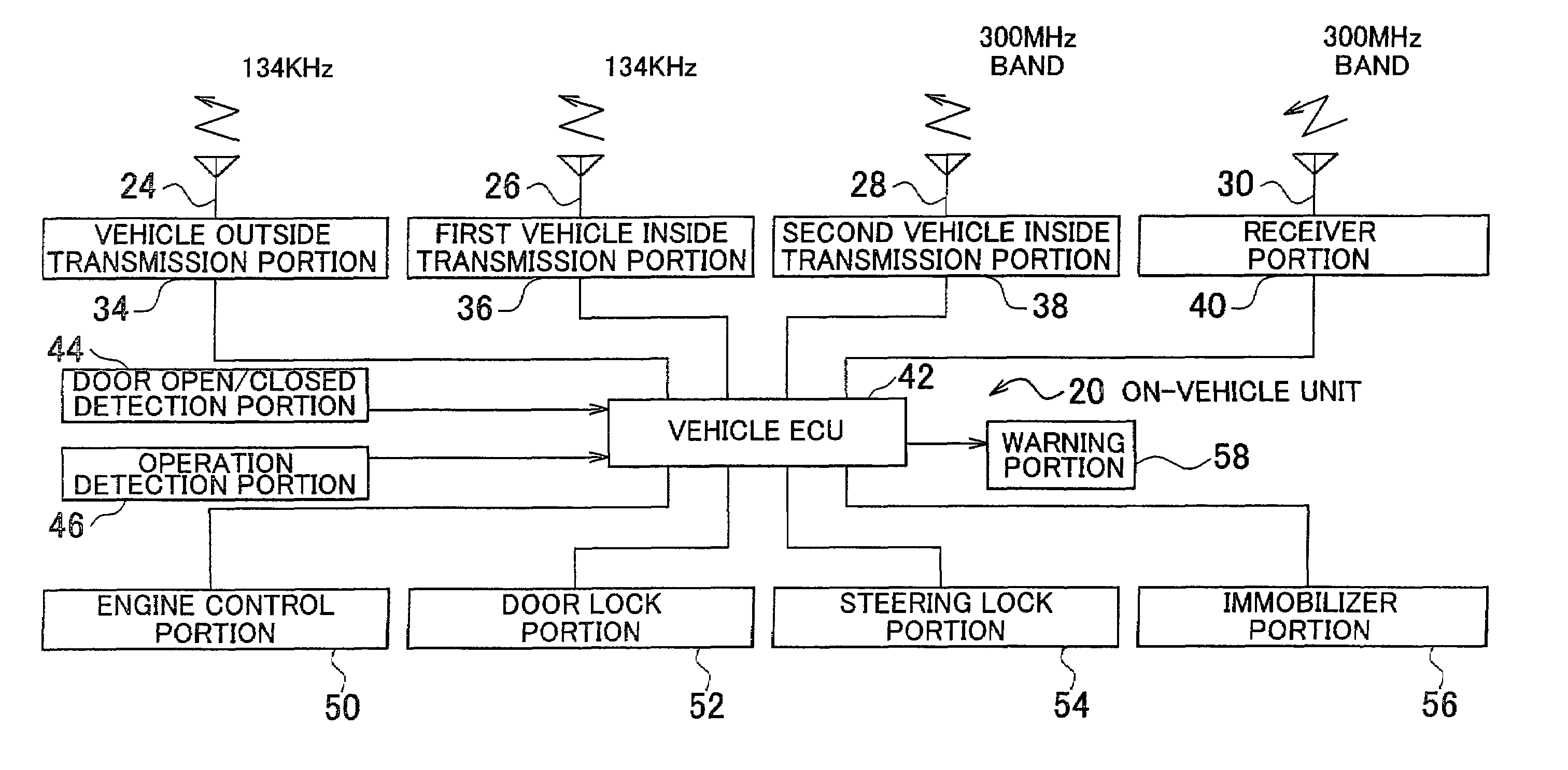
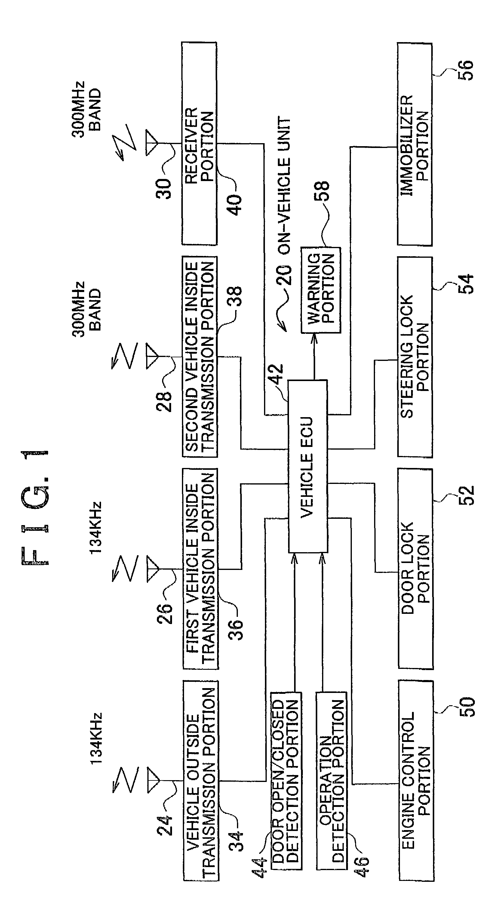
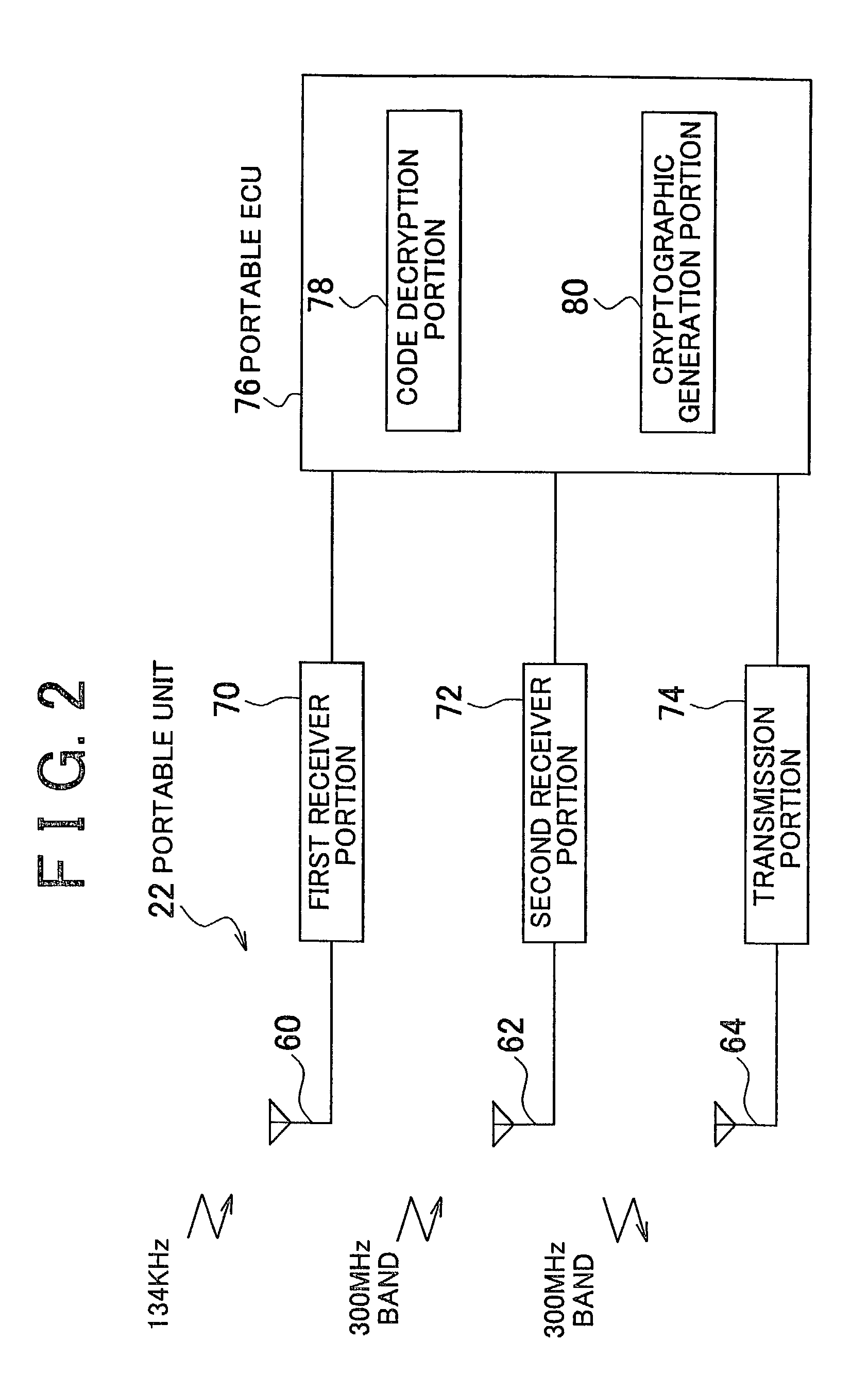
[0031]FIG. 1 is a view showing a configuration of an on-vehicle unit 20 provided in an on-vehicle equipment remote control system according to the invention. FIG. 2 is a view showing a configuration of a portable unit 22 provided in the on-vehicle equipment remote control system. The on-vehicle unit 20 is mounted into a vehicle. The on-vehicle unit 20 controls equipment (explained later) using wireless communication with the portable unit 22 that a vehicle operator carries, without involving an operation by the vehicle operator.

[0032]As FIG. 1 shows, the on-vehicle unit 20 has a vehicle outside transmission antenna 24, a first vehicle inside transmission antenna 26, a second vehicle inside transmission antenna 28 and a receiver antenna 30. The vehicle outside antenna 24 is provided, for example, on an outer handle of a manually operated vehicle door that is used when the vehicle operator enters, loads or unloads the vehicle. It has an effective communication area with a radius of, f...

second embodiment

[0073]Next, the invention will be explained with reference to FIG. 7 and the aforementioned FIGS. 1 and 2. A system according to this embodiment of the invention is realized through execution of a routine shown in FIG. 7 by the vehicle ECU 42 of the on-vehicle unit 20 in the configurations shown in FIGS. 1 and 2.

[0074]According to the first embodiment of the invention, the downlink communication from the on-vehicle unit 20 to the portable unit 22 that takes place on execution of the engine start control prior to the start of the engine utilizes only the low frequency radio wave (134 kHz). According to the second embodiment of the invention, the on-vehicle unit 20 is able to communicate utilizing both the comparatively low frequency radio wave (134 kHz) and the high frequency radio wave (300 MHz). Furthermore, taking into consideration that the portable unit 22 is able to receive both radio waves, the downlink communication utilizes both the low frequency radio wave and the high freq...

third embodiment

[0088]Next, the invention will be explained with reference to FIG. 8 and the aforementioned FIGS. 1, 2 and 7. A system according to this embodiment of the invention is realized through execution of a routine shown in FIG. 8 in place of the routine shown in FIG. 7 by the vehicle ECU 42 of the on-vehicle unit 20 in the configurations shown in FIGS. 1 and 2.

[0089]According to the second embodiment of the invention, unless the collation of the downlink communication that utilized the 134 kHz frequency radio wave is completed and, after that, the collation of the downlink communication that utilized the 300 MHz frequency radio wave is completed, then engine start is not permitted. According to the third embodiment of the invention, at the point when the collation of the downlink communication that utilized the 134 kHz frequency radio wave is completed, engine start is permitted and the collation of the downlink communication that utilized the 300 MHz frequency radio wave is carried out i...


PUM


Abstract

In an on-vehicle equipment remote control system provided with a portable unit that a vehicle operator can carry and an on-vehicle unit that executes a predetermined process if a code content of a response signal issued by the portable unit in response to a transmitted request signal matches a required code content, the on-vehicle unit transmits the request signal on a first frequency prior to the start of a vehicle power source and transmits the request signal on a second frequency that is higher than the first frequency after the start of the vehicle power source.

Description

INCORPORATION BY REFERENCE[0001]The disclosure of Japanese Patent Application No. 2001-394562 filed on Dec. 26, 2001 including the specification, drawings and abstract is incorporated herein by reference in its entirety.BACKGROUND OF THE INVENTION[0002]1. Field of Invention[0003]The invention relates to a remote control system for on-vehicle equipment and a remote control method. More specifically, this invention relates to a remote control system for on-vehicle equipment that includes a portable unit and an on-vehicle unit that executes a predetermined process when a code content of a response signal issued by the portable unit in response to a transmitted request signal matches a required code content, and a remote control method for the same.[0004]2. Description of Related Art[0005]An on-vehicle equipment remote control system provided with a portable unit and an on-vehicle unit, which controls permission or non-permission of use of a vehicle based on the result of a code collati...

Claims


Application Information

Patent Timeline
IPC IPC(8): G05B19/00G06F7/00G06K19/00G08B29/00E05B49/00B60R25/01B60R25/04B60R25/104B60R25/20B60R25/24H04Q9/00H04Q9/10
CPCB60R25/24B60R25/2072
Inventor OKADA, HIROKI
Owner TOYOTA JIDOSHA KK
Why Eureka
Try Eureka