Cabinet cooling

a technology for cabinets and cooling cabinets, applied in the field of cooling cabinets, can solve the problems of increasing the complexity of the ejector having moveable parts, poor performance, and no real breakthrough, and achieve the effects of reducing the number of cooling cabinets

Inactive Publication Date: 2006-06-13
TELEFON AB LM ERICSSON (PUBL)
View PDF14 Cites 40 Cited by
  • Summary
  • Abstract
  • Description
  • Claims
  • Application Information

AI Technical Summary

Benefits of technology

[0008]A general object of the invention is to provide an improved method of cooling a cabinet containing heat dissipating electronic components. In particular, it is an object of the invention to provide a cooling method being able to handle high heat loads very efficiently, at comparatively low cost and with minimum power consumption.
[0009]Briefly, the above object is achieved by controlling the circulation of a cooling medium in a closed system containing an evaporator, a condenser, an ejector and control valves. Specifically, this object of the invention is accomplished by providing controlling the valves of the system based on a detected heat load in the cabinet and / or on detected heat transfer conditions, thereby continuously allowing the system to operate in the most appropriate mode. Expressed otherwise, the invention provides an automatic adaptation of the mode of operation of the system based on the actual prevailing conditions, so that a unique flexibility is obtained with regard to the cooling mode in which the system will be operated. This means that the cooling capacity will be constantly optimized and that the cost, both with regard to the investment and to the operation of the system, will be reduced compared to known systems having equal maximum cooling capacity.
[0012]When detecting heat load conditions near or at a maximum a control unit initiates a further mode of operation. Such conditions will cause automatic activation of an ejector cooling mode comprising vacuum compression by means of an ejector. Once more, this will maintain optimum performance under the changed conditions. This cooling mode will comprise forced circulation of the cooling medium and will allow a restricted flow of cooling medium from the condenser to the evaporator where the cooling medium is vaporized. The restricted flow is controlled based on the detected conditions, allowing the remainder of the cooling medium flow from the condenser to be circulated to a primary side of the ejector under a low positive pressure. A negative pressure is created at a secondary side of the ejector to pump vaporized cooling medium from the evaporator for condensation. In this way a very cost effective operation of the cooling system will be achieved through low energy consumption as well an extended optimization of the system performance.
[0019]Very cost effective and also environmentally friendly by being energy-saving and allowing the use of e.g. water or alcohol as working medium;

Problems solved by technology

A common problem with all such ejector refrigeration systems has been the poor heat factor of the ejector heat pump, resulting in a likewise poor performance.
So far no real breakthrough has been made and many known ejector systems are designed to be operated by waste heat, such as excess heat from solar energy facilities, and to operate at supersonic speeds.
A major drawback of this solution is the increased complexity of the ejector having moveable parts, namely a miniature rotor intended to perform the actual pressure exchange.

Method used


Image

  • Cabinet cooling
  • Cabinet cooling
  • Cabinet cooling

Examples


Embodiment Construction

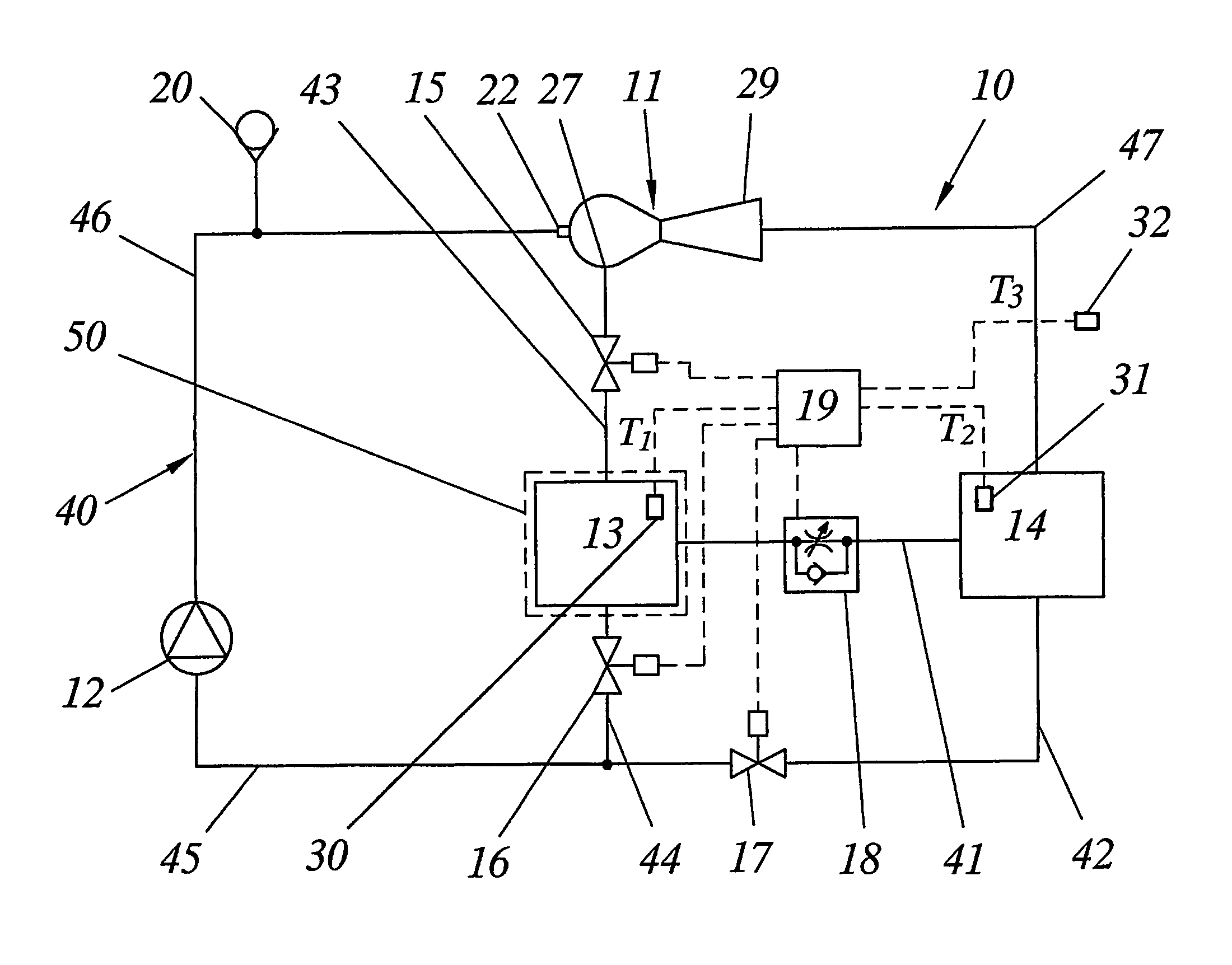
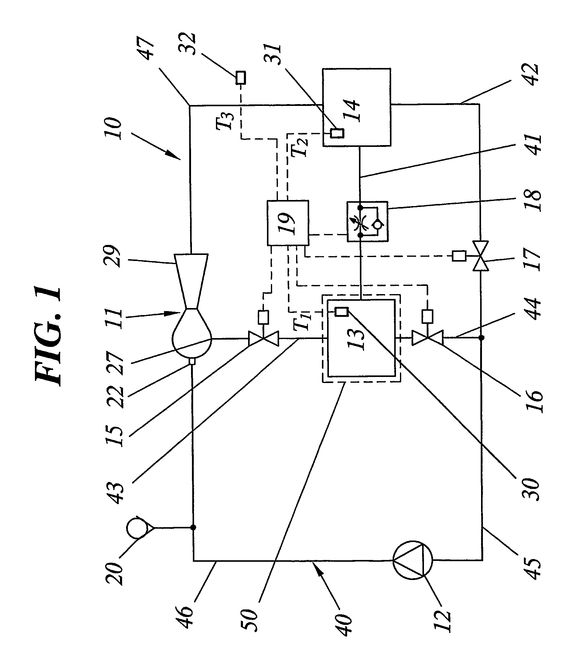
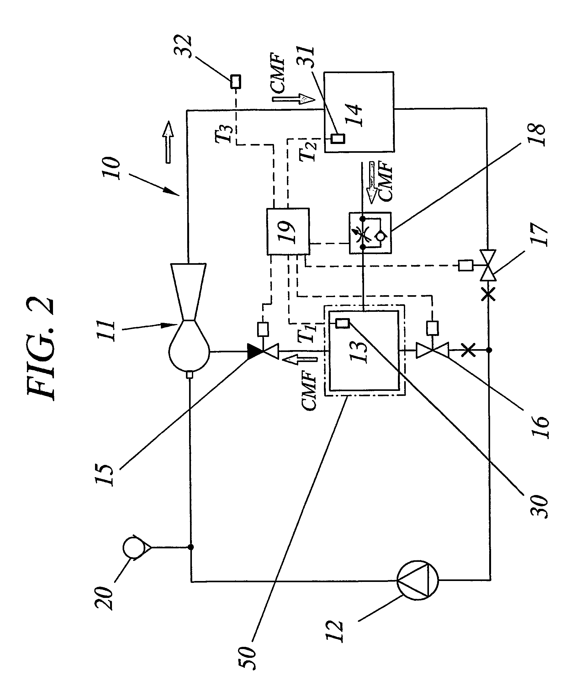
[0033]The basic principles of the invention shall now be described by means of an embodiment of a cooling system 10 for performing the suggested method of cooling a cabinet 50 containing heat dissipating electronic components. The electronic components may be in the form of printed board assemblies PBA, see FIGS. 5A and 5B, or others. Within this specification the expression “printed board assembly” refers to a printed circuit board with modules and / or components mounted thereon. The general layout of said system is schematically illustrated in FIG. 1. The cooling system 10 is closed or hermetic and filled with a liquid cooling medium that may also be referred to as a refrigerant. Suitable cooling mediums for use with this system are e.g. water, alcohol, ammonia, benzol or other environmentally friendly medium having a vaporizing temperature of 25–100° C. at a slight subatmospheric pressure or at atmospheric pressure.

[0034]The system comprises a condenser / heat exchanger unit 14 prov...


PUM


Abstract

A novel electronics cooling method and system is disclosed. A very flexible and efficient operation of an electronics cooling system (10) is achieved by controlling circulation of a cooling medium in a closed system (40) containing an evaporator (13), a condenser (14), an ejector (11) and control valves (15–18). Specifically, the system is continuously allowed to operate in the most appropriate mode by controlling the valves (15–18) of the system (10) based on detected heat load and / or detected heat transfer conditions. By automatically adapting the mode of operation of the system based on the actual prevailing conditions, a unique flexibility is obtained with regard to the cooling mode in which the system will be operated. This means that the cooling capacity will be constantly optimized and that the investment cost as well as the cost for operating the system will be reduced compared to known systems having equal maximum cooling capacity.

Description

TECHNICAL FIELD[0001]The present invention generally concerns methods and systems for cooling cabinets containing heat producing electronic equipment.BACKGROUND[0002]An important factor in the design of hardware, is the provision of adequate cooling of the electronic components employed therein. This is especially the case when designing hardware for use within the modem telecom and datacom industries. In this area it is an absolute requirement that the electronic components that are normally integrated in a cabinet are maintained at normal temperatures. Failure to do so will at least impair the operation and / or functionality of components or even cause them to fail completely.[0003]Additionally, energy consumption during the life cycle of electronic products has the most important environmental and economical impact. Lower energy consumption is a strong sales argument and will be even more important in the future. Energy cost for cooling the electronics during ten-fifteen years is ...

Claims


Application Information

Patent Timeline
Patent Type & Authority Patents(United States)
IPC IPC(8): H05K7/20F25B1/06F25B23/00G05D19/00G05D23/19
CPCF25B1/06F25B23/006H05K7/20381G05D23/1931F25B2700/2106F25B2700/2117F25B2700/2116
Inventor TSOI, VADIM
Owner TELEFON AB LM ERICSSON (PUBL)
Why Eureka
Try Eureka