
High performance server farm with tagging and pipelining

Active Publication Date: 2006-06-13
CITRIX SYST INC
View PDF21 Cites 120 Cited by
  • Summary
  • Abstract
  • Description
  • Claims
  • Application Information

AI Technical Summary

Benefits of technology

[0012]In one embodiment, the invention provides a network flow switch that is coupleable between a communications network and a data server farm. In one configuration, the network flow switch is configured as a Layer 2, 3, and 4 Web switch and assumes the global IP addresses of a server farm and receives all transaction requests from clients on behalf of the server farm. A “transaction request” refers to any signal, whether or not in the form of a packet, that requests or otherwise initiates work by one or more servers, such as causing the server(s) to provide requested information stored in the memory of the server(s) or to compute information based on information referenced or provided by the signal. The switch inspects any combination of URL and content type to route requests and set access priority; parses to determine the requested URL; selects the best able server to retrieve the content; and thereby builds a URL database of source server with reference count (or hit counter) and expiration timer (or time stamp). Repeated requests are directed to the same server, which may be a cacheable server. Using content reference count and the expiration timer, the switch can calculate the combination of access frequency and recency and thereby detect the “hot” content. Frequently requested content is thereby efficiently segregated and cached even among a cluster configuration of network flow switches.
[0026]Finally, a cluster of switches can be employed as the switches are highly scalable. Digest information and / or tagging information is shared by the various switches in the cluster. This sharing provides not only redundancy but also scalability.

Problems solved by technology

Businesses are rapidly becoming computer and network dependent.
Down times and slow and / or erroneous responses can lead to customer frustration and sales losses.
This switching technique can be problematic in a Web environment.
Web switches, however, have problems.
For example, Web switches can unnecessarily parse a packet for a number of packet fields.
Server farms also fail to use the information collected by the Web switch in organizing content for rapid access.
As a result, requests can take longer to process than is necessary.

Method used


Image

  • High performance server farm with tagging and pipelining
  • High performance server farm with tagging and pipelining
  • High performance server farm with tagging and pipelining

Examples


Embodiment Construction

The Components of the Network Switch

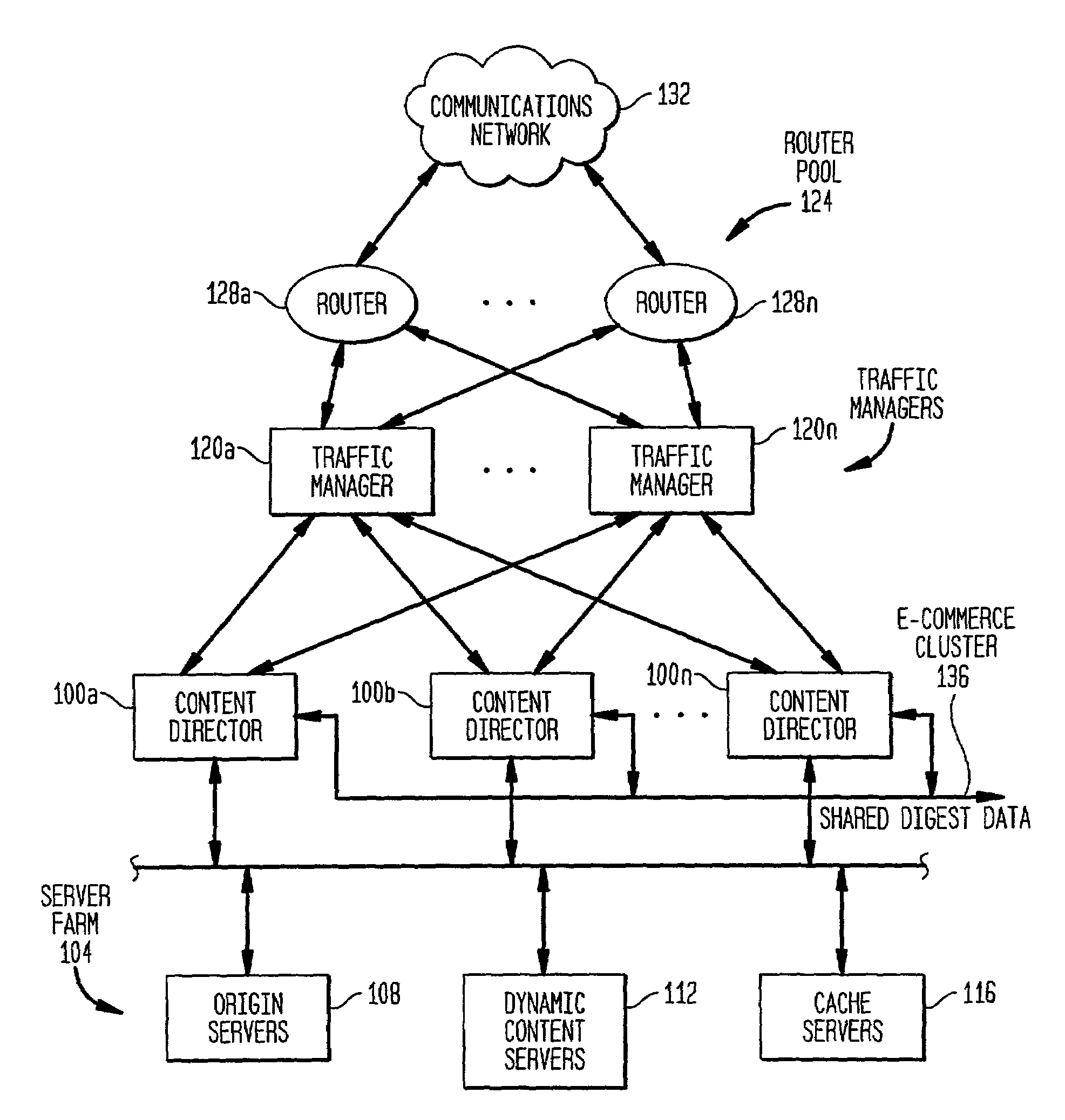
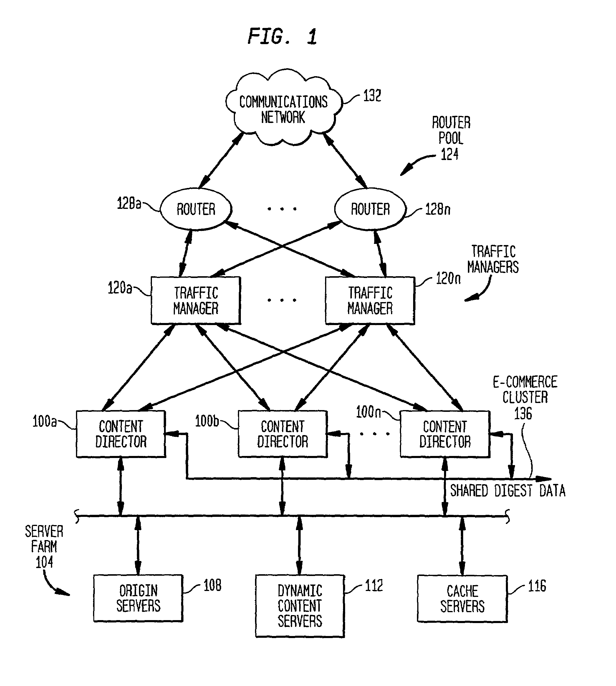
[0037]The present invention is preferably embodied as a server computer system identified as a content director server in FIG. 1. Multiple content director servers 100a–n are grouped together as a cluster to support, in a preferred embodiment, e-commerce-type HTTP transactions. A server farm 104 includes origin server(s) 108, dynamic content server(s) 112 and / or cache server(s) 116. Traffic managers 120a–n perform load balancing by known techniques across the cluster of content directors. A router pool 124 including routers 128a–n route packets from the communications network 132 to the traffic managers 120a–n.

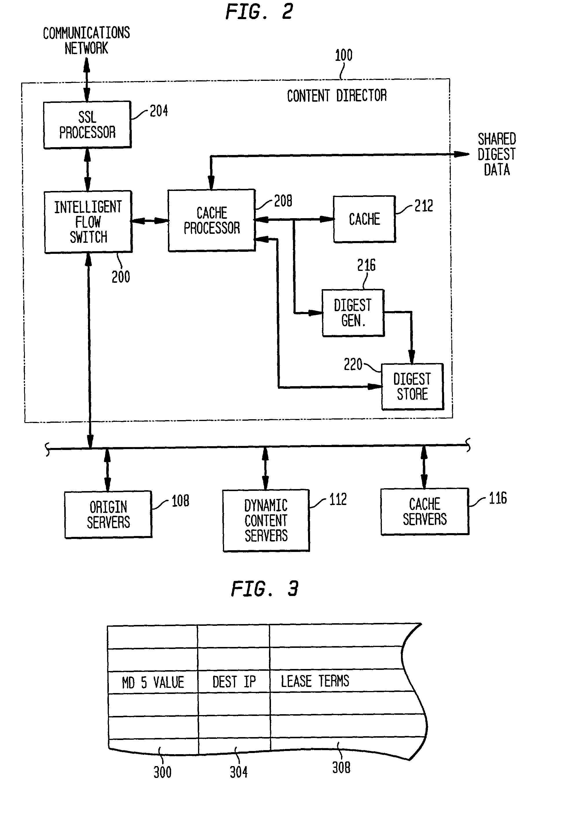
[0038]Each content director server, as generally shown in FIG. 2, includes an intelligent flow switch 200 for efficiently routing HTTP transactions based on invariants in and associated with IP data packets. An decryption or SSL processor 204 is optionally provided to off-load encryption and decryption operations involved in both secure ses...


PUM


Abstract

The present invention is directed to a network switch that determines when specific content is hot and directs flow to one or more cache servers. The architecture can include a tag generator to generate unique tags corresponding to a server in a plurality of servers, a content pre-fetching algorithm to retrieve information before the information is requested by determining the hotness of the information, and a cache server in which stored information is configured based upon the relative degrees of hotness of the stored information.

Description

CROSS REFERENCE TO RELATED APPLICATIONS[0001]The present application claims the benefits under 35 U.S.C.§119(e) of U.S. Provisional Application Ser. No. 60 / 223,087, of the same title, filed Aug. 4, 2000, which is incorporated herein by reference in its entirety. The present application is related to U.S. Patent Applications entitled “Intelligent Demand Driven Recognition of URL Objects in Connection Oriented Transactions” and “Non-Intrusive Multi-plex Transaction Persistency and Secure Commerce Environments”, both of which are filed concurrently herewith and have the same named inventors as the present application.FIELD OF THE INVENTION[0002]The present invention relates generally to load balancing, network switches, and particularly to network switches capable of performing intelligent load balancing of flows while maintaining transaction coherency.BACKGROUND OF THE INVENTION[0003]Businesses are rapidly becoming computer and network dependent. Web technology is adding momentum to E...

Claims


Application Information

Patent Timeline
IPC IPC(8): G06F15/173H04L12/28H04L12/56H04L12/50H04Q11/00G06F12/00G06F15/00H04L29/06H04L29/08H04L29/12
CPCH04L29/06H04L45/566H04L61/2015H04L61/30H04L61/301H04L63/0428H04L63/0464H04L63/12H04L67/2804H04L67/2847H04L67/1008H04L67/34H04L67/1027H04L67/2895H04L67/2814H04L67/2819H04L67/1006H04L67/02H04L67/2842H04L67/1002H04L67/327H04L67/2852H04L67/1014H04L67/1012H04L67/1017H04L67/1023H04L67/288H04L29/12594H04L69/329H04L63/166H04L2029/06054H04L2463/102H04L67/10015H04L61/5014H04L67/561H04L67/564H04L67/563H04L67/1001H04L67/5681H04L67/5682H04L67/63H04L67/568H04L9/40
Inventor HONG, JACKCHU, ALBERT BONYAOJASWA, VIJAY
Owner CITRIX SYST INC
Learn More