Imaging lens

a compact, lens technology, applied in the field of compact imaging lenses, can solve the problems of difficult to reduce shorten the total length of the lens system, and difficult to keep the angle of emergence small, and achieve the effect of superior optical characteristics

Inactive Publication Date: 2006-06-20
COPAL CO LTD
View PDF5 Cites 11 Cited by
  • Summary
  • Abstract
  • Description
  • Claims
  • Application Information

AI Technical Summary

Benefits of technology

[0009]The present invention overcomes the problems described above and provides a bright (with a small F number) imaging lens with superior optical characteristics wherein, by using an extremely simple three-group, three-lens structure and setting the lens shapes and aspherical surface shapes appropriately, it is possible to have a compact, thin, light-weight design that can be used for solid-state imaging elements with one million pixels or more and that can be installed in portable devices such as portable telephones and personal digital assistants.

Problems solved by technology

This makes it difficult to reduce the angle of emergence and to keep the total length of the lens system short.
Also, in the imaging lens described in Japanese Laid-Open Patent Publication Number Hei 05-188284, the aperture stop is disposed furthest toward the object side, but since there is no inflection point on the aspherical surface of the third lens or in the lens system, it is difficult to keep the angle of emergence small and to keep the total length of the lens system short.

Method used


Image

  • Imaging lens
  • Imaging lens
  • Imaging lens

Examples


first embodiment

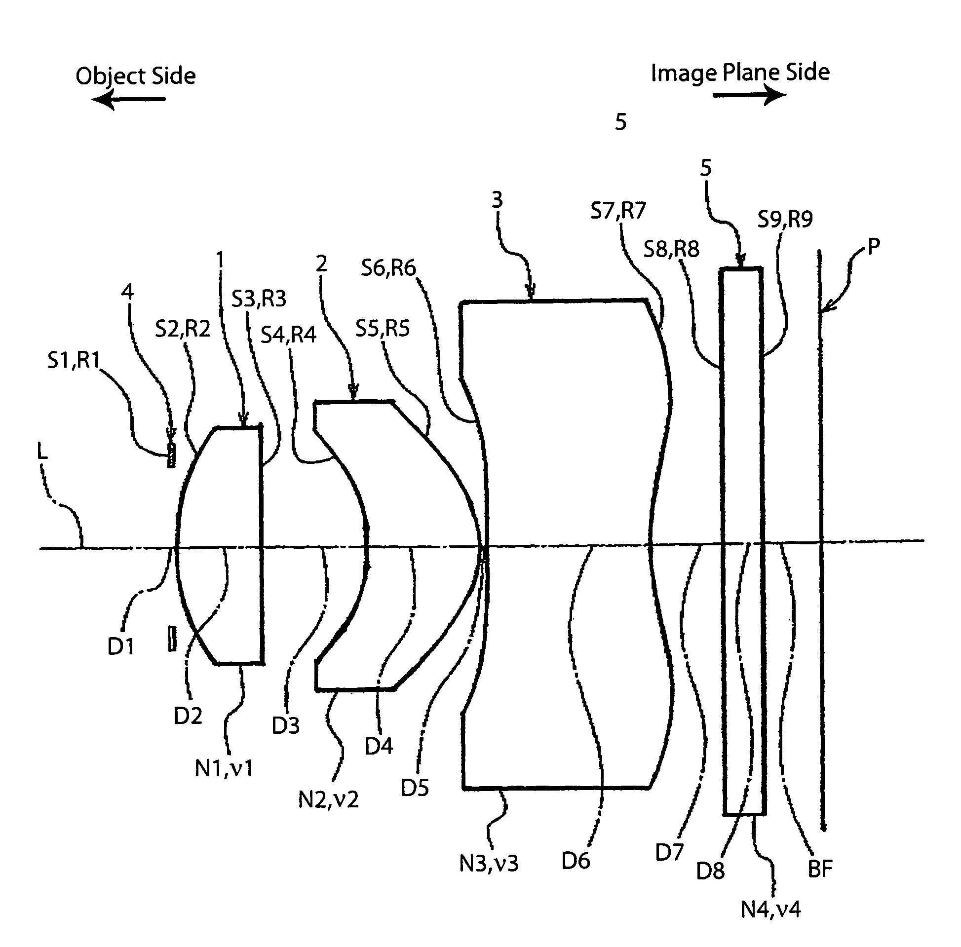
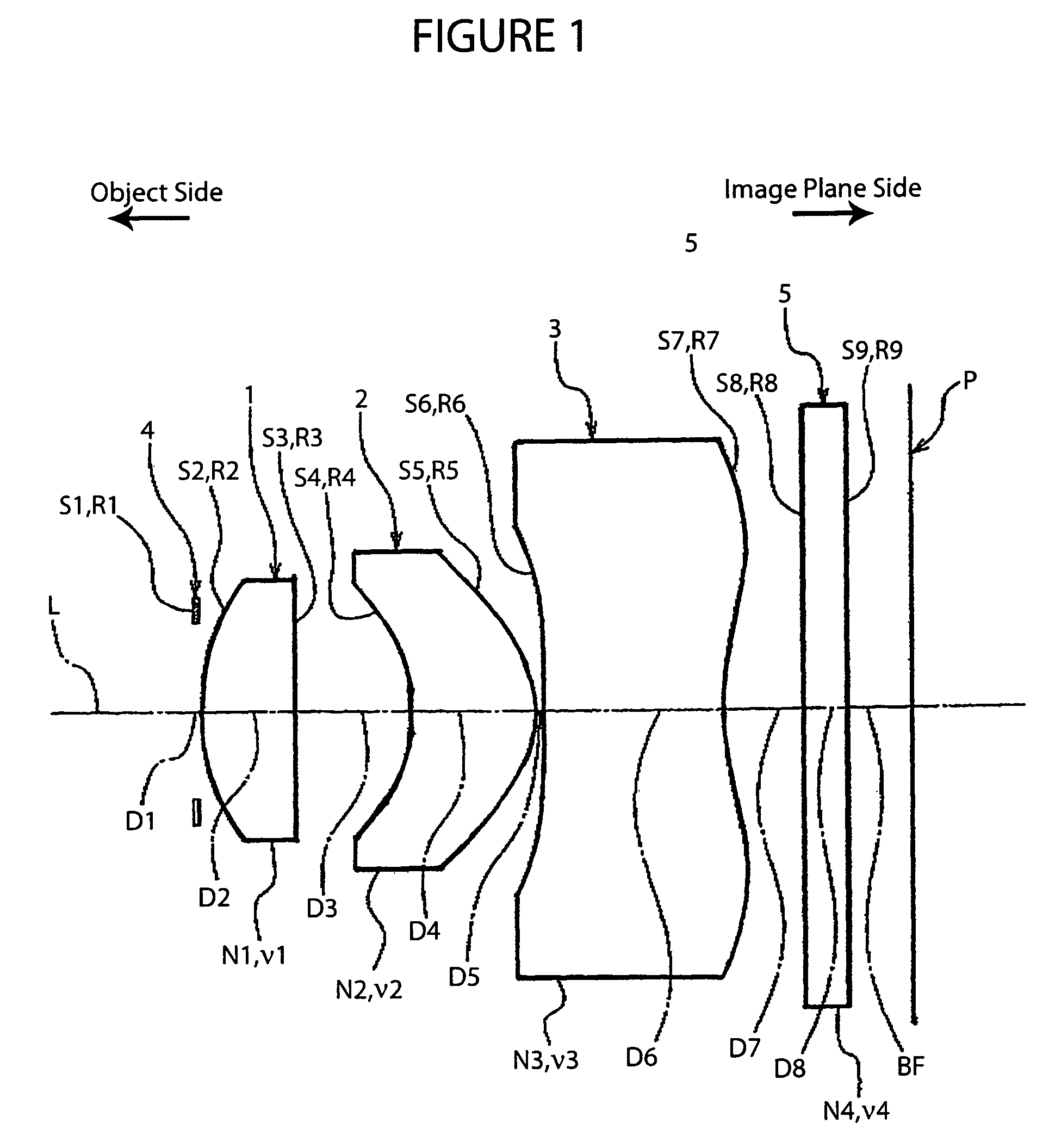
[0037]FIG. 1 shows the basic structure of a lens system according to the imaging lens of the present invention.

[0038]As shown in FIG. 1, this imaging lens includes the following elements along an optical axis L, going from the object side to the image plane side: an aperture stop 4 having a predetermined diameter, a first lens 1 with a convex surface facing toward the object side having an overall positive refractive power, a second lens 2 with a concave surface facing toward the object side having an overall positive refractive power, and a third lens 3 with a concave surface facing toward the object side having an overall negative refractive power. Also, in the arrangement described above, a glass filter 5, e.g., an infrared cut filter or a low-pass filter, is disposed behind the third lens 3, and an image plane P, e.g., a CCD, is disposed behind that.

[0039]More specifically, the imaging lens is formed with a three-group, three-lens structure, with the first lens group formed by t...

second embodiment

[0067]FIG. 3 shows the basic structure of a lens system according to the Table 4 shows the main specifications. Table 5 shows various numerical data (settings). Table 6 shows numerical data relating to the aspherical surfaces.

[0068]In this working example, the numerical data for the conditions (1)–(6) are as follows:

TL / f=7.648 / 5.83=1.31;  (1)

v1=70.2, v2=56.4, v3=30.3;  (2)

|R4| / |R5|=1.54;  (3)

|R6| / |R7|=7.79;  (4)

D5 / f=0.017; and  (5)

D4 / D6=0.70.  (6)

[0069]

TABLE 4Focal Length f5.83Total Length TL of Lens System7.648(mm)(air conversion distance usedfor D8 (glass filter 5))(mm)F Number2.89Back Focus1.83(FNo.)(Air Conversion)(mm)Field Angle63.4°Object Distanceinfinity (∞)(2ω)

[0070]

TABLE 5Curvature RadiusDistanceIndex of RefractionAbbeSurface(mm)(mm)(d line)NumberS1R1∞Aperture StopD10.000S2R22.701D21.050N1ν1S3R359.2211.4874970.2D31.278S4*R4−2.150D41.394N2ν2S5*R5−1.3961.5091456.4D50.100S6*R6−22.638D61.996N3ν3S7*R72.9061.5838530.3D70.850S8R8∞D80.500N4ν4S9R9∞1.5168064.2BF0.650*aspherical surf...

third embodiment

[0073]FIG. 5 shows the basic structure of a lens system according to the Table 7 shows the main specifications. Table 8 shows various numerical data (settings). Table 9 shows numerical data relating to the aspherical surfaces.

[0074]In this embodiment, the numerical data for the conditions (1)–(6) are as follows:

TL / f=7.62 / 5.78=1.32;  (1)

v1=70.2, v2=56.4, v3=30.3;  (2)

|R4| / |R5|=1.53;  (3)

|R6| / |R7|=9.13;  (4)

D5 / f=0.017; and  (5)

D4 / D6=0.71.  (6)

[0075]

TABLE 7Focal Length f5.78Total Length TL of Lens System7.620(mm)(air conversion distance usedfor D8 (glass filter 5))(mm)F Number2.89Back Focus1.85(FNo.)(Air Conversion)(mm)Field Angle64.1°Object Distanceinfinity (∞)(2ω)

[0076]

TABLE 8Curvature RadiusDistanceIndex of RefractionAbbeSurface(mm)(mm)(d line)NumberS1R1∞Aperture StopD10.000S2R22.707D21.050N1ν1S3R366.6311.4874970.2D31.229S4*R4−2.141D41.407N2ν2S5*R5−1.3961.5091456.4D50.100S6*R6−26.318D61.984N3ν3S7*R72.8831.5838530.3D70.850S8R8∞D80.500N4ν4S9R9∞1.5168064.2BF0.670*aspherical surface

[00...


PUM


Abstract

The present invention includes, from an object side to an image-plane side: an aperture stop with a predetermined diameter, a first lens with a positive refractive power having a convex surface on the object side, a second lens with a positive refractive power having a concave surface on the object side, and a third lens with a negative refractive power having a convex surface on the object side. The second and third lenses have aspherical surfaces on their object-side and image-plane-side surfaces. The third lens is formed with an inflection point where the curvature orientation changes within the effective diameter range of the aspherical surface on the image-plane side. An appropriate back focus is maintained while the total length of the lens system is reduced. A compact, thin, high-performance design is achieved, which effectively corrects various aberrations, especially astigmatism and distortion, and is suited for digital cameras using high-density solid-state imaging elements of one million pixels or more.

Description

INCORPORATION BY REFERENCE[0001]The present application claims priority under 35 U.S.C. §119 to Japanese Patent Application No. 2004-231257 filed on Aug. 6, 2004. The content of the application is incorporated herein by reference in its entirety.FIELD OF THE INVENTION[0002]The present invention relates to a compact imaging lens used in digital still cameras and digital video cameras and the like equipped with a solid-state imaging element such as CCD (Charge Coupled Device) or CMOS (complementary metal oxide semiconductor). More specifically, the present invention relates to an imaging lens suitable for a compact mobile camera installed in a portable device such as a portable telephone, personal digital assistant (PDA), or portable personal computer.BACKGROUND OF THE INVENTION[0003]In recent years, there have been advances in the technology for solid-state imaging elements that include not only CCDs but also CMOS elements. For solid-state imaging elements in digital still cameras, t...

Claims


Application Information

Patent Timeline
Patent Type & Authority Patents(United States)
IPC IPC(8): G02B9/12
CPCG02B13/0035G02B9/12
Inventor MURAKAMI, KAZUYAABE, YASUHIKO
Owner COPAL CO LTD
Why Eureka
Try Eureka