Automatic gain control circuit and an RF receiver and method using such a circuit

a gain control circuit and gain control technology, applied in the direction of radio transmission, transmission monitoring, electrical equipment, etc., can solve the problems that the prior art loop described in the reference is not suitable for use in narrow band rf receivers or transceivers, and achieves wide variation of dynamic range and overshoot, fast attack, and efficient operation.

Inactive Publication Date: 2006-06-20
MOTOROLA SOLUTIONS INC
View PDF12 Cites 18 Cited by
  • Summary
  • Abstract
  • Description
  • Claims
  • Application Information

AI Technical Summary

Benefits of technology

[0035]The present invention beneficially provides a novel AGC circuit, receiver incorporating the same and a method of operating the receiver to provide a fast attack automatic gain for narrow band systems with a response time of 0.5 ms or less, in many cases 0.2 ms or less, making the circuit, receiver and method suitable for use in detecting RF signals provided in discontinuous bursts in a TDMA system, especially when operating in DMO. In particular, the AGC circuit according to the invention beneficially allows a receiver incorporating it to deal efficiently with the above described wide variation of dynamic range and overshoot permitted in TDMA systems such as TETRA DMO as well as minimising the overshoot caused internally by its own response process.

Problems solved by technology

However, the prior art loop described in the said reference is not suitable for use in narrow band RF receivers or transceivers, e.g. for use in TDMA, in which the RF power is received in discontinuous bursts, such as in the TETRA Direct Mode Operation (DMO) because the response time of the loop is not sufficiently fast.

Method used


Image

  • Automatic gain control circuit and an RF receiver and method using such a circuit
  • Automatic gain control circuit and an RF receiver and method using such a circuit
  • Automatic gain control circuit and an RF receiver and method using such a circuit

Examples


Embodiment Construction

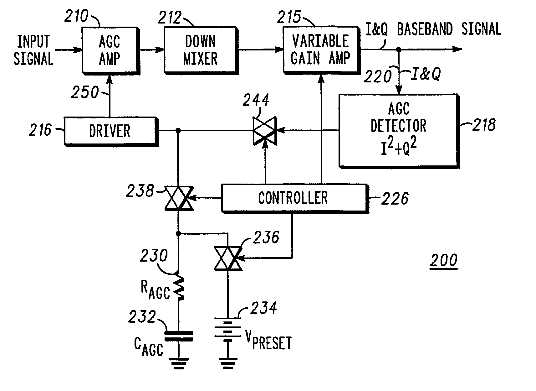
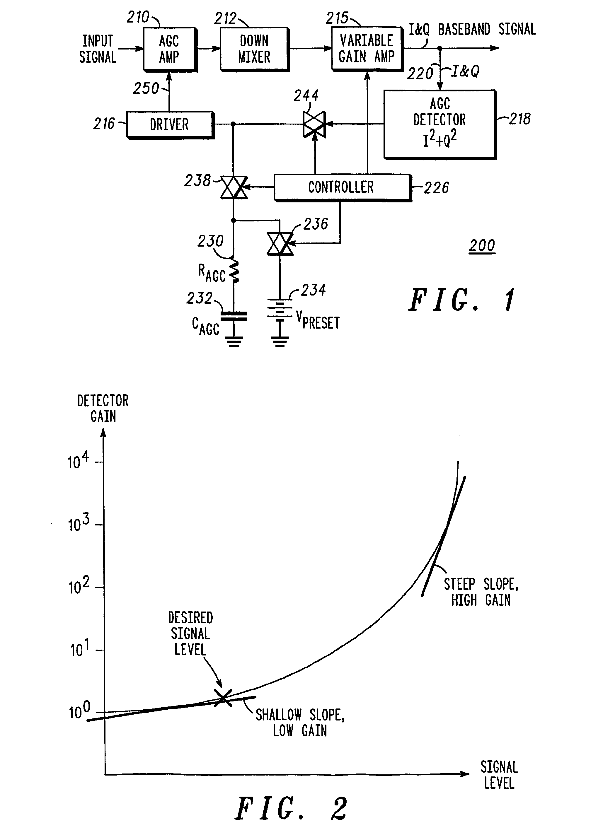
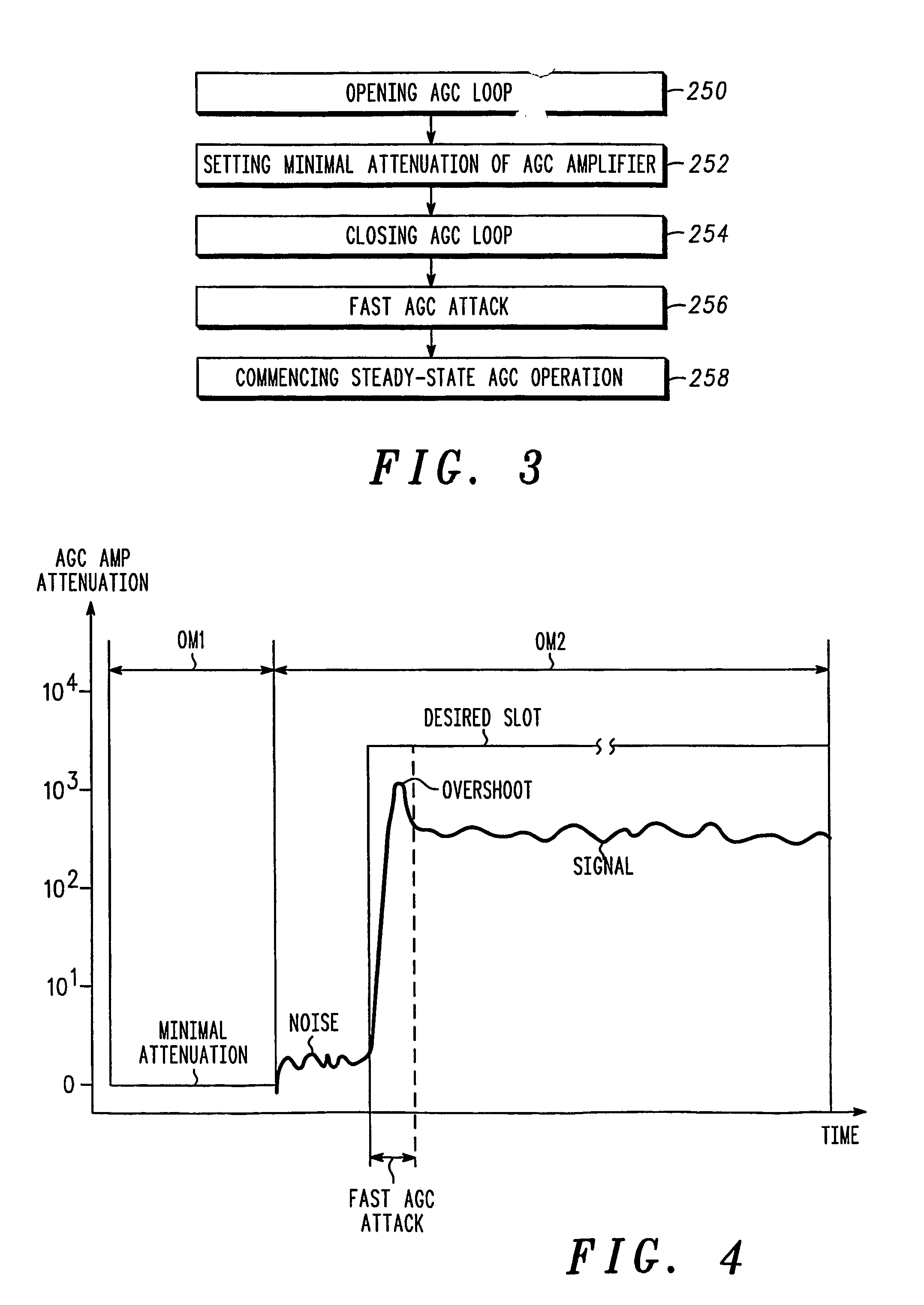
[0044]Reference is now made to FIG. 1, which is a schematic illustration of a fast attack AGC loop, generally referenced 200, constructed and operable in accordance with an embodiment of the present invention.

[0045]AGC loop 200 includes an AGC amplifier 210 in a forward transmission path 214, a down mixer 212 and a variable gain amplifier 215 also in the forward transmission path 214, a driver 216, an AGC detector 218, a controller 226, a damping resistor RAGC 230, an integrating capacitor CAGC 232, a voltage source VPRESET 234 and three switches 236, 238 and 244. AGC amplifier 210 is coupled to down mixer 212 and to driver 216. The down mixer 212 is coupled to the variable gain amplifier 215. The AGC detector 218 is coupled via a connection 220 to the variable gain amplifier and at its output to switch 244. Controller 226 is coupled to switches 236, 238 and 244 and also to variable gain amplifier 215. Driver 216 is coupled to switches 238 and 244. Voltage source VPRESET 234 is coup...


PUM


Abstract

An automatic gain control (AGC) circuit including: a forward transmission path (214) having applied at its input an input RF signal and to provide at its output an output signal; a variable gain AGC amplifier (210) in the forward transmission path for processing the input RF signal, which amplifier has a control input 240 and is responsive to a control signal applied at its control input to vary its gain; a feedback loop (220 to 240), coupled from the output of the forward transmission path and to the control input of the AGC amplifier; an integrator (230, 232), coupled to the control input of the amplifier; a voltage source (234), coupled to the integrator and to the control input of the amplifier; and a further variable gain device (215) for varying the gain or attenuation of a signal applied to the control input of the AGC amplifier.

Description

[0001]This application claims the benefit of prior filed co-pending international application Ser. No. PCT / EP02 / 06061 filed May. 3, 2002, and assigned to Motorola, Inc., which was published by the International Bureau on Apr. 10, 2003 under No. WO 03 / 030356 A2 and Great Britain application Ser. No. 0123500.1 filed Sep. 29, 2001.FIELD OF THE INVENTION[0002]The present invention relates to an automatic gain control circuit and an RF receiver and a method using such a circuit.BACKGROUND OF THE INVENTION[0003]A radio communication system includes, as a minimum, a transmitter and a receiver. The transmitter and the receiver (which are often each part of combined transceiver unit) are interconnected by a radio-frequency (RF) wireless channel, which provides transmission of a communication signal between them. A receiver generally includes an amplifier, which is coupled to a receiving element (an antenna). The amplifier has a gain, which can be adjusted in a predetermined range, using a co...

Claims


Application Information

Patent Timeline
Patent Type & Authority Patents(United States)
IPC IPC(8): H04B1/06H03G3/20H03G3/30
CPCH03G3/3052H03G3/3078
Inventor BEN-AYUN, MOSHEROZENTAL, MARKPASTERNAK, ROMANAVAYU, IZAK
Owner MOTOROLA SOLUTIONS INC
Why Eureka
Try Eureka