Gas sensor

a technology of gas sensor and sensor body, which is applied in the field of gas sensor, can solve the problems of inferior thermal resistance of materials, the possibility of exceeding the thermal resistance limit of materials sensitive to (weak in) heat, and the inability to withstand heat, so as to reduce the heat transmission and reduce the risk of radiant heat , the effect of less raisability

Active Publication Date: 2006-06-27
DENSO CORP
View PDF8 Cites 9 Cited by
  • Summary
  • Abstract
  • Description
  • Claims
  • Application Information

AI Technical Summary

Benefits of technology

[0017]In the gas sensor according to the present invention, a region of the emissivity being equal to or lower than 0.3 is provided on the atmosphere surface, thereby reducing the heat transmission stemming from the radiant heat with respect to the atmosphere surface so that the temperature of the gas sensor becomes less r

Problems solved by technology

Meanwhile, of the components of a gas sensor, there are materials inferior in thermal resistance.
However, this elastic insulating material is made of a resin or a rubber and is inferior in thermal resistance.
The radiant heat promotes heating the gas sensor so that there is a possibility of exceeding the thermal resistance limit of a material sensitive to (

Method used


Image

  • Gas sensor
  • Gas sensor
  • Gas sensor

Examples


first embodiment

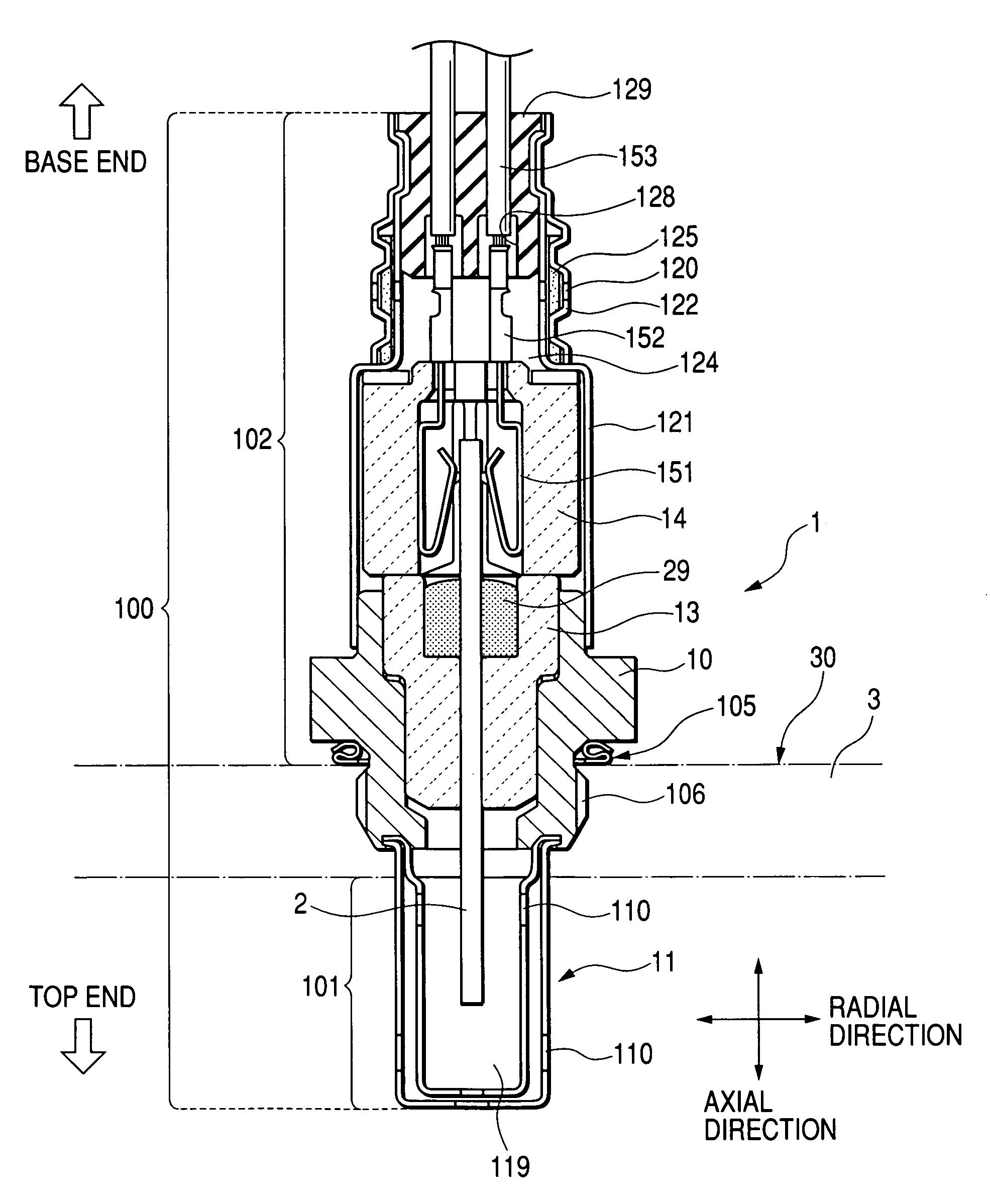
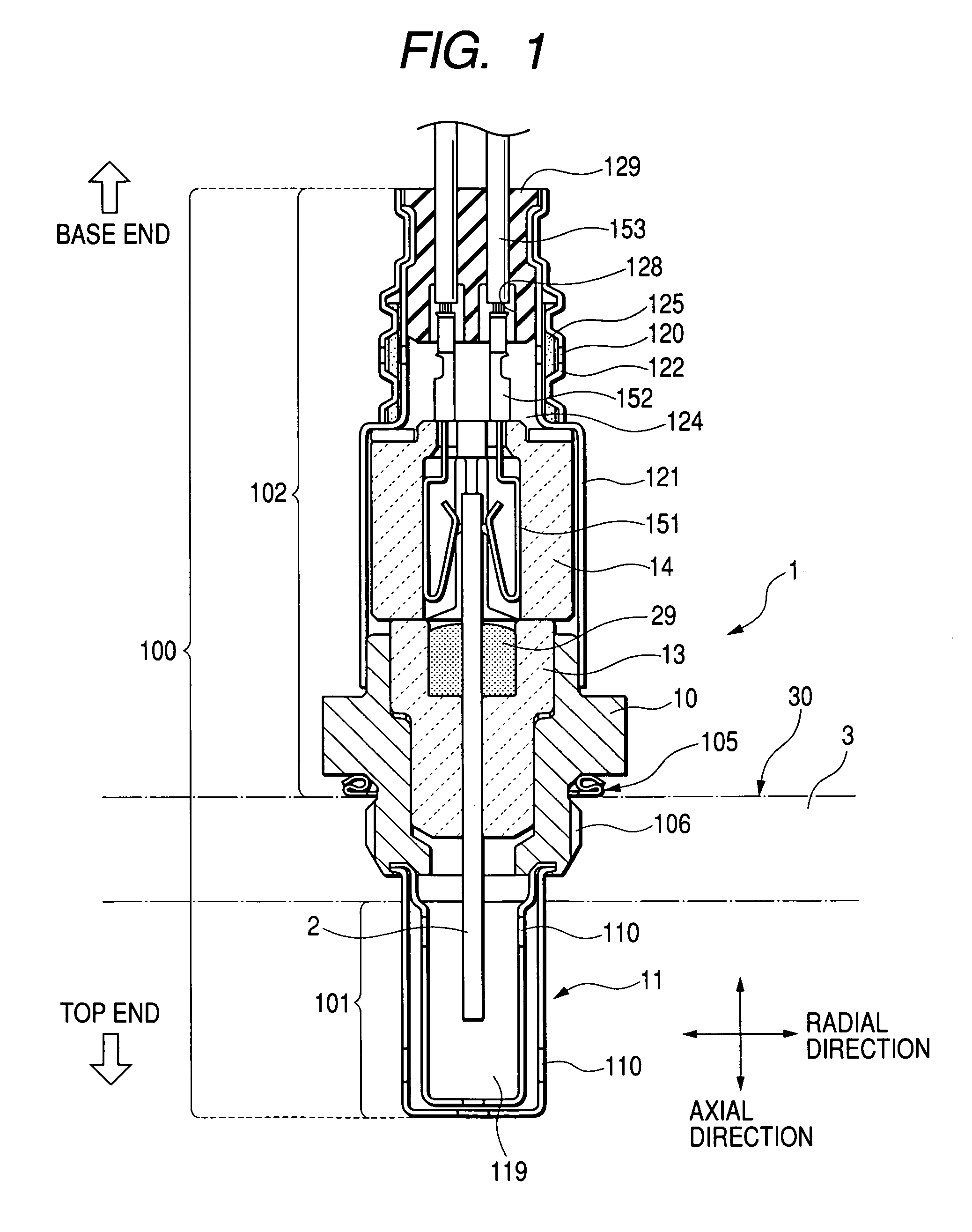
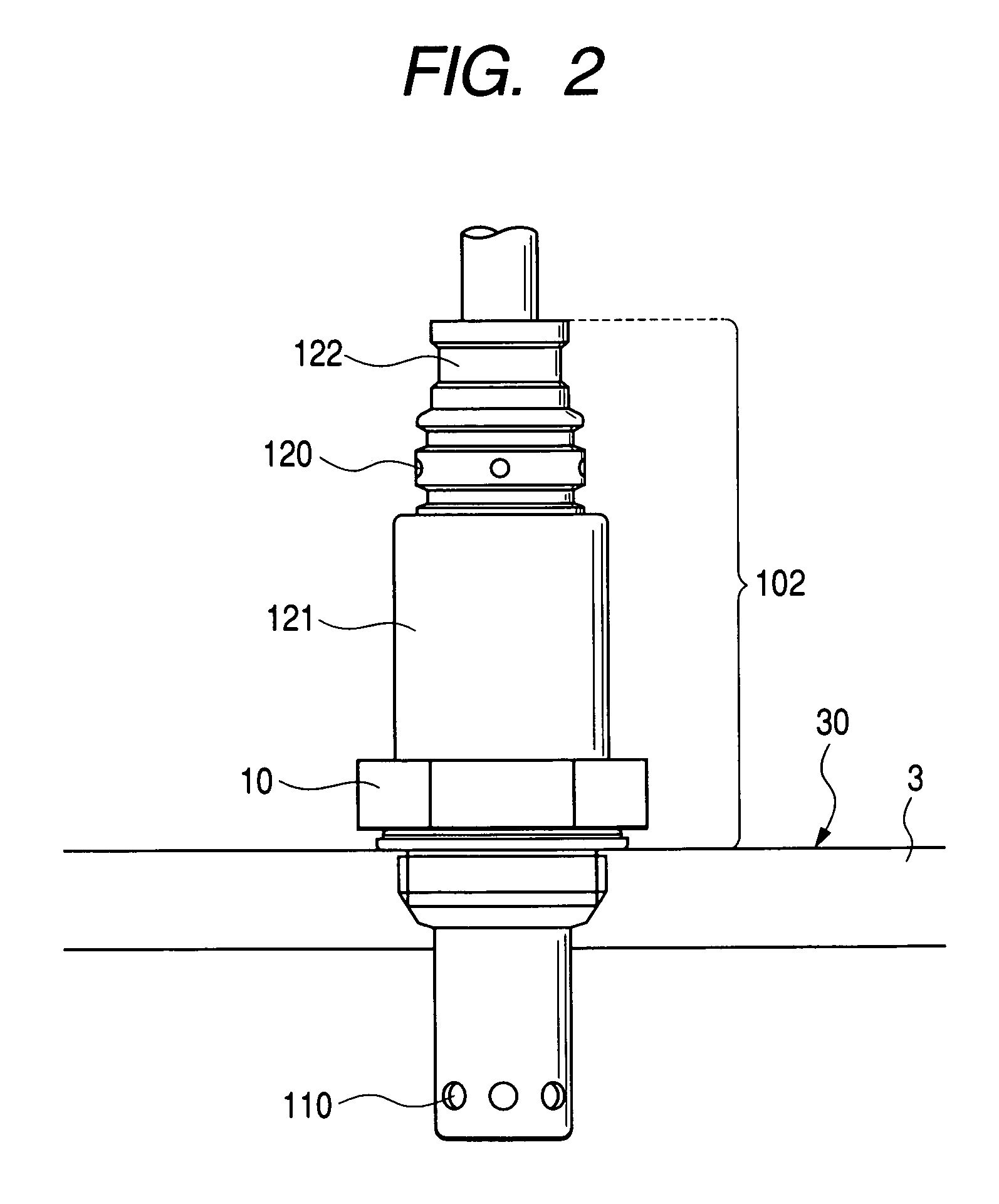
[0050]As shown in FIGS. 1 and 2, a gas sensor according to this embodiment, generally designated at reference numeral 1, internally includes a sensing element 2 for measuring a specific gas concentration in a measured gas, and an outer surface 100 of the gas sensor 1 has a measured gas surface 101 exposed to a measured gas and an atmosphere surface 102 exposed to the atmosphere. The emissivity of at least a portion of the atmosphere surface 102 is equal to or lower than 0.3.

[0051]A detailed description will be given hereinbelow of the gas sensor 1 according to this embodiment.

[0052]As FIG. 1 shows, the gas sensor 1 according to this embodiment is made such that a housing 10 is threadly fixed to a screw portion of a gas sensor fixing hole made in an exhaust pipe 3 of a vehicle engine and a portion of the top end of the gas sensor 1 is exposed to the exhaust gas to measure an air-fuel ratio in a combustion chamber (not shown) of the vehicle engine on the basis of an oxygen concentrati...

second embodiment

[0079]According to this embodiment, in the gas sensor with the construction according to the first embodiment, the emissivity of the atmosphere surface or the area of the region whose emissivity is low is changed and the temperature rise suppression effect are measured.

[0080]A sample 0 is a reference sample in which a passive-state film is formed on the atmosphere surface without forming a shot-blast-treated surface and the metallic shiny slightly appears but the emissivity of the atmosphere surface is as high as 0.4.

[0081]The atmosphere surface of a sample 1 does not have formed passive-state film, and the metallic shiny of SUS 310 directly appears.

[0082]On the atmosphere surface of a sample 3, a passive-state film is sufficiently formed by heating.

[0083]The atmosphere surface of a sample 2 has a treated surface formed by shot-blast-treating an atmosphere surface which is in the state of the sample 3.

[0084]In each of gas sensors based on the samples 1 to 3, the emissivity of the en...


PUM


Abstract

In a gas sensor internally including a sensing element for measuring a specific gas concentration of a measured gas, an outer surface thereof has a measured gas surface exposed to a measured gas and an atmosphere surface exposed to the atmosphere, and at least a portion of the atmosphere surface has an emissivity equal to or lower than 0.3. Preferably, this emissivity is a value with respect to an electromagnetic wave having a wavelength of 0.5 to 1 μm, and the a region of the atmosphere surface, contributing 60% or more of the atmosphere surface, has an emissivity equal to or lower than 0.3. This provides a gas sensor less susceptible to radiant heat and less temperature-increasable.

Description

BACKGROUND OF THE INVENTION[0001]1) Field of the Invention[0002]The present invention relates to a gas sensor made to measure an oxygen concentration or the like in an exhaust gas from an engine for a vehicle for the purpose of utilizing the measurement result for the combustion control or the like.[0003]2) Description of the Related Art[0004]The combustion control based on the oxygen concentration or the like in the exhaust gas from a vehicle engine works effectively for the fuel consumption and the efficient exhaust gas purification.[0005]A gas sensor for detecting the oxygen concentration or the like in the exhaust gas internally includes a sensing element for measuring a specific gas concentration of a measured gas (gas to be measured).[0006]This gas sensing element has an electrochemical cell comprising a solid electrolyte and a pair of electrodes and is made to measure an oxygen concentration or the like in a measured gas on the basis of an electromotive force occurring betwee...

Claims


Application Information

Patent Timeline
IPC IPC(8): G01N7/12G01N1/22G01N27/409G01N27/407
CPCG01N27/407G01N1/2252
Inventor YAMADA, HIROKAZU
Owner DENSO CORP
Why Eureka
Try Eureka