Mobile wireless communications device comprising multi-frequency band antenna and related methods

a wireless communication and multi-frequency band technology, applied in the field of mobile wireless communication devices, can solve the problems of phone antennas, difficult use of mobile devices, and relatively close proximity to the user's head, and achieve the effect of small device sizes

Active Publication Date: 2006-06-27
GOOGLE TECH HLDG LLC
View PDF41 Cites 53 Cited by
  • Summary
  • Abstract
  • Description
  • Claims
  • Application Information

AI Technical Summary

Benefits of technology

[0011]In view of the foregoing background, it is therefore an object of the present invention to provide a mobile wireless communications device including an antenna configuration which allows for relatively small device sizes, yet provides desired performance over multiple frequency bands.
[0013]The multi-frequency band antenna may therefore be arranged to take up a relatively small footprint yet still provide desired performance. Moreover, the antenna configuration allows for convenient positioning at the bottom of a mobile device (e.g., cellular phone) printed circuit board (PCB), which aids in complying with applicable SAR requirements. This configuration may also allow for less impact on antenna performance due to blockage by a user's hand. That is, users typically hold cellular phones toward the middle to upper portion of the phone housing, and are therefore more likely to put their hands over such an antenna than they are an antenna positioned adjacent the lower portion of the housing.
[0014]The main loop conductor may have a generally rectangular shape with opposing first and second sides and opposing first and second ends, and the gap may be in the first side of the main loop conductor. Moreover, the respective first ends of the first branch conductor, the second branch conductor, and the tuning branch conductor may be connected to the first side of the main loop conductor. In particular, the main loop conductor may include non-planar portions to provide further space savings, for example.

Problems solved by technology

External antennas may be cumbersome and make the mobile device difficult to use, particularly in limited-space environments.
Yet, one potential drawback of typical internal cellular phone antennas is that they are in relatively close proximity to the user's head when the phone is in use.
The amount of RF energy absorbed by a body when using a mobile phone is called the specific absorption rate (SAR), and the allowable SAR for mobile phones is typically limited by applicable government regulations to ensure safe user RF energy exposure levels.

Method used


Image

  • Mobile wireless communications device comprising multi-frequency band antenna and related methods
  • Mobile wireless communications device comprising multi-frequency band antenna and related methods
  • Mobile wireless communications device comprising multi-frequency band antenna and related methods

Examples


Embodiment Construction

[0026]The present invention will now be described more fully hereinafter with reference to the accompanying drawings, in which preferred embodiments of the invention are shown. This invention may, however, be embodied in many different forms and should not be construed as limited to the embodiments set forth herein. Rather, these embodiments are provided so that this disclosure will be thorough and complete, and will fully convey the scope of the invention to those skilled in the art. Like numbers refer to like elements throughout, and prime notation is used to indicate similar elements in alternate embodiments.

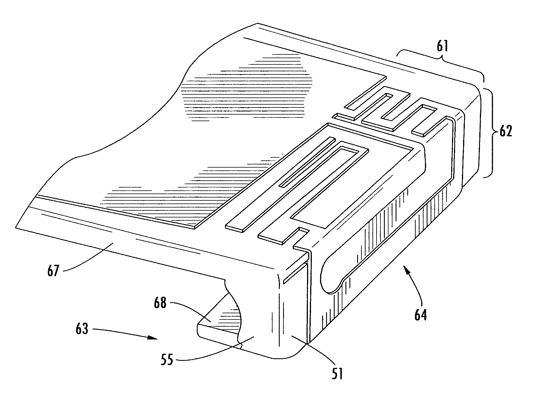
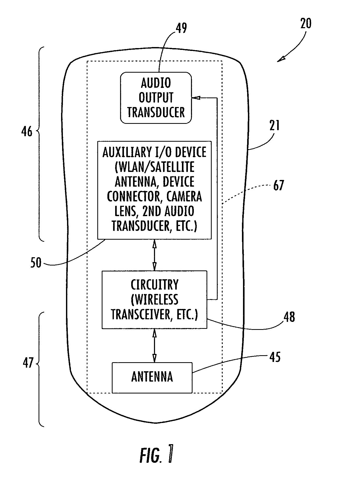
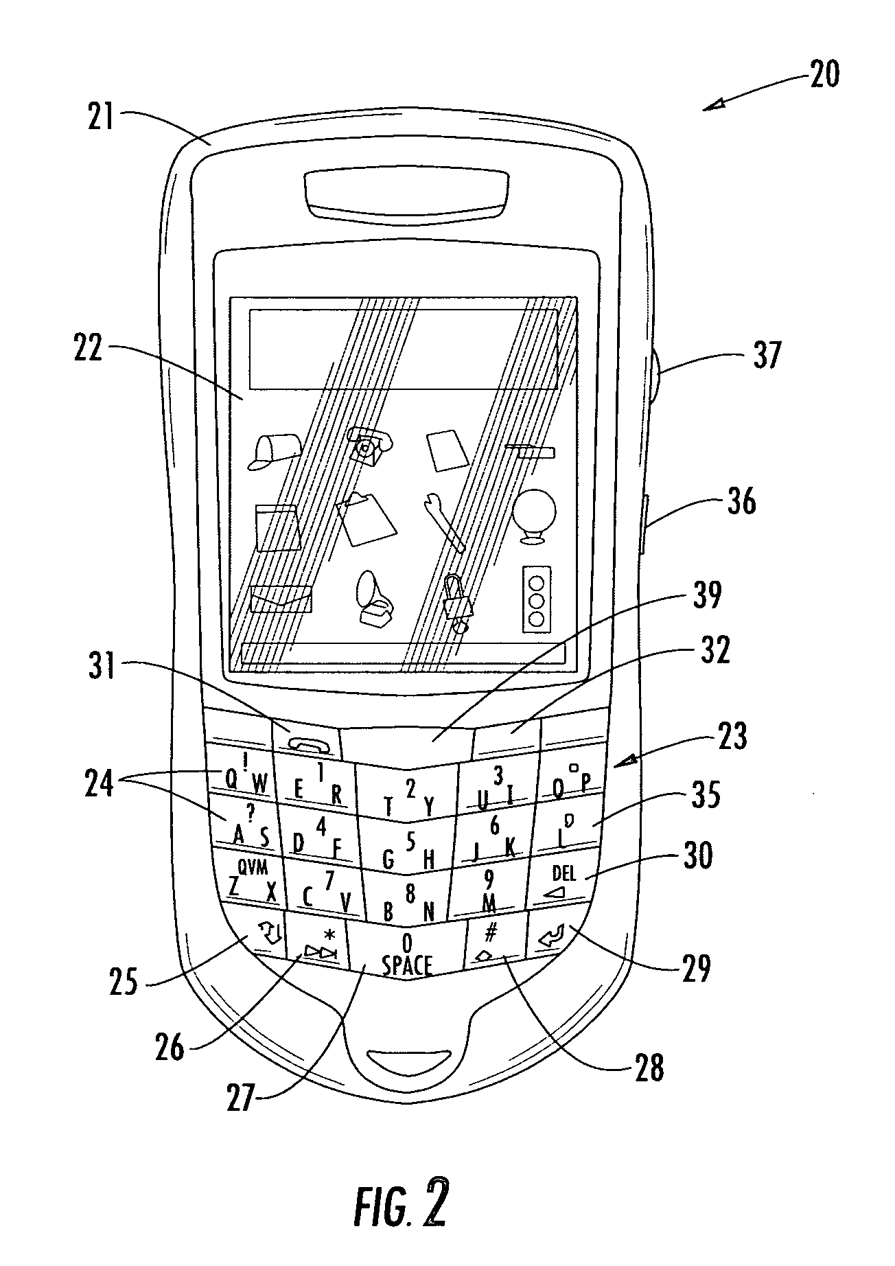
[0027]Referring initially to FIGS. 1 and 2, a mobile wireless communications device, such as a mobile cellular device 20, in accordance with the present invention is first described. The cellular device 20 illustratively includes a housing 21 having an upper portion 46 and a lower portion 47, and a main dielectric substrate 67, such as a printed circuit board (PCB) substrate,...


PUM

PropertyMeasurementUnit
frequenciesaaaaaaaaaa
heightaaaaaaaaaa

Abstract

A mobile wireless communications device may include a housing and a multi-frequency band antenna carried within the housing. The multi-frequency band antenna may include a main loop conductor having a gap therein defining first and second ends of the main loop conductor, a first branch conductor having a first end connected adjacent the first end of the main loop conductor and having a second end defining a first feed point, and a second branch conductor having a first end connected adjacent the second end of the main loop conductor and a second end defining a second feed point. The antenna may further include a tuning branch conductor having a first end connected to the main loop conductor between the respective first ends of the first and second branches.

Description

CROSS-REFERENCE TO RELATED APPLICATIONS[0001]This application claims the benefit of U.S. Provisional Application Nos. 60 / 576,159 filed Jun. 2, 2004, and 60 / 576,637, filed Jun. 3, 2004, both of which are hereby incorporated herein in their entireties by reference.FIELD OF THE INVENTION[0002]The present invention relates to the field of communications devices, and, more particularly, to mobile wireless communications devices and related methods.BACKGROUND OF THE INVENTION[0003]Cellular communications systems continue to grow in popularity and have become an integral part of both personal and business communications. Cellular telephones allow users to place and receive voice calls most anywhere they travel. Moreover, as cellular telephone technology has increased, so too has the functionality of cellular devices. For example, many cellular devices now incorporate personal digital assistant (PDA) features such as calendars, address books, task lists, etc. Moreover, such multi-function d...

Claims


Application Information

Patent Timeline
Patent Type & Authority Patents(United States)
IPC IPC(8): H01Q1/24H01Q1/36H01Q1/38H01Q5/00H01Q5/10H01Q5/371H01Q7/00H01Q9/04H01Q9/40H01Q9/42H04B1/38H04B1/3827H04Q7/32
CPCH01Q1/243H01Q1/36H01Q1/38H01Q7/00H01Q5/371H01Q9/40H01Q9/42H01Q9/0407H04B1/3833Y10T29/49016H01Q1/24H01Q5/00
Inventor QI, YIHONGMAN, YING TONGJARMUSZEWSKI, PERRY
Owner GOOGLE TECH HLDG LLC
Why Eureka
Try Eureka