

Optical sampling waveform measuring apparatus
a waveform and optical technology, applied in the direction of optical apparatus testing, instruments, structural/machine measurement, etc., can solve the problems of unstable optical properties, unstable optical properties, and inability to use values for a sampled optical, and achieve low timing jitter, high timing resolution, and stable low timing jitter
- Summary
- Abstract
- Description
- Claims
- Application Information
AI Technical Summary
Benefits of technology
Problems solved by technology
Method used
Image

Examples
first embodiment
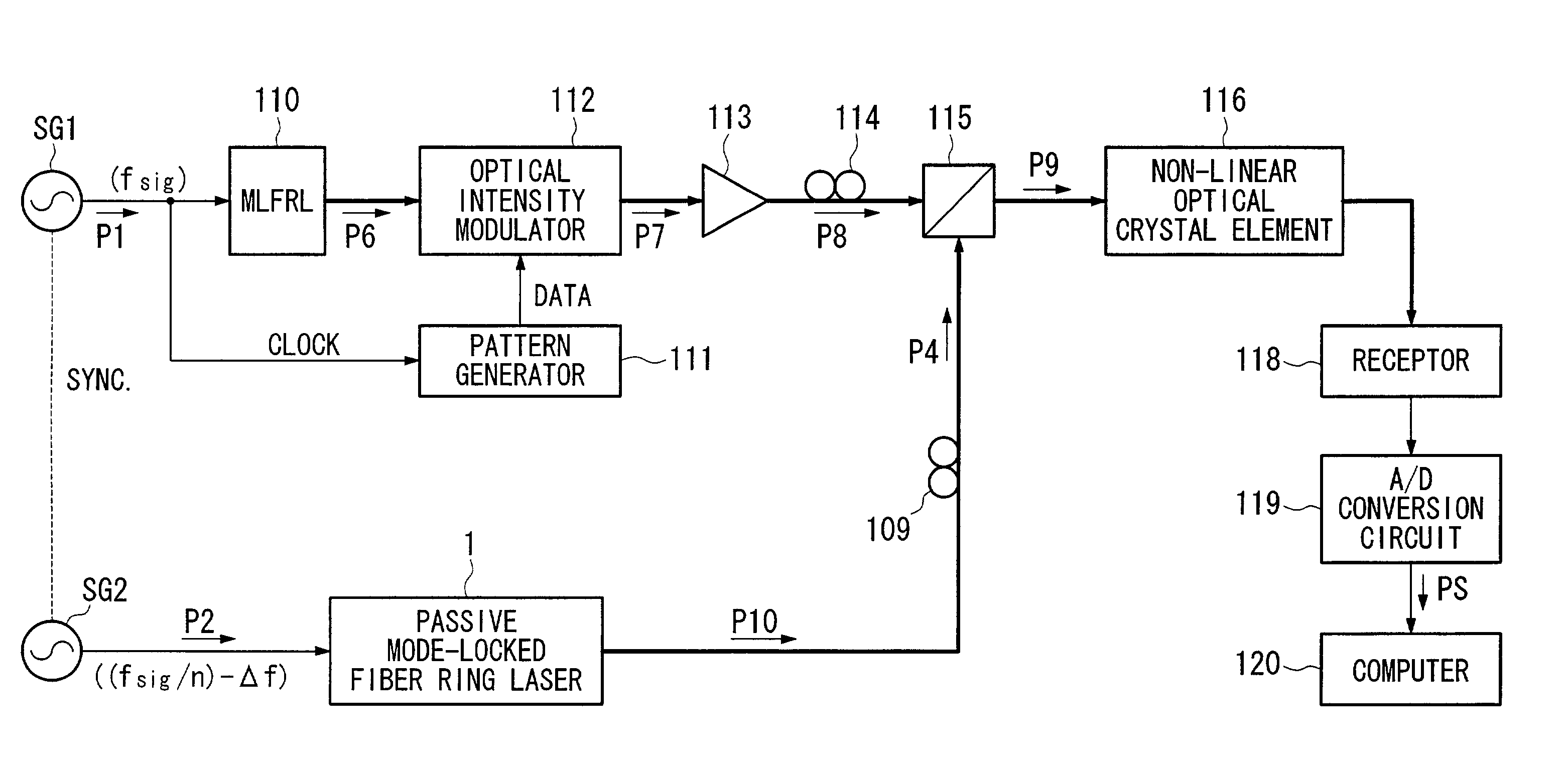
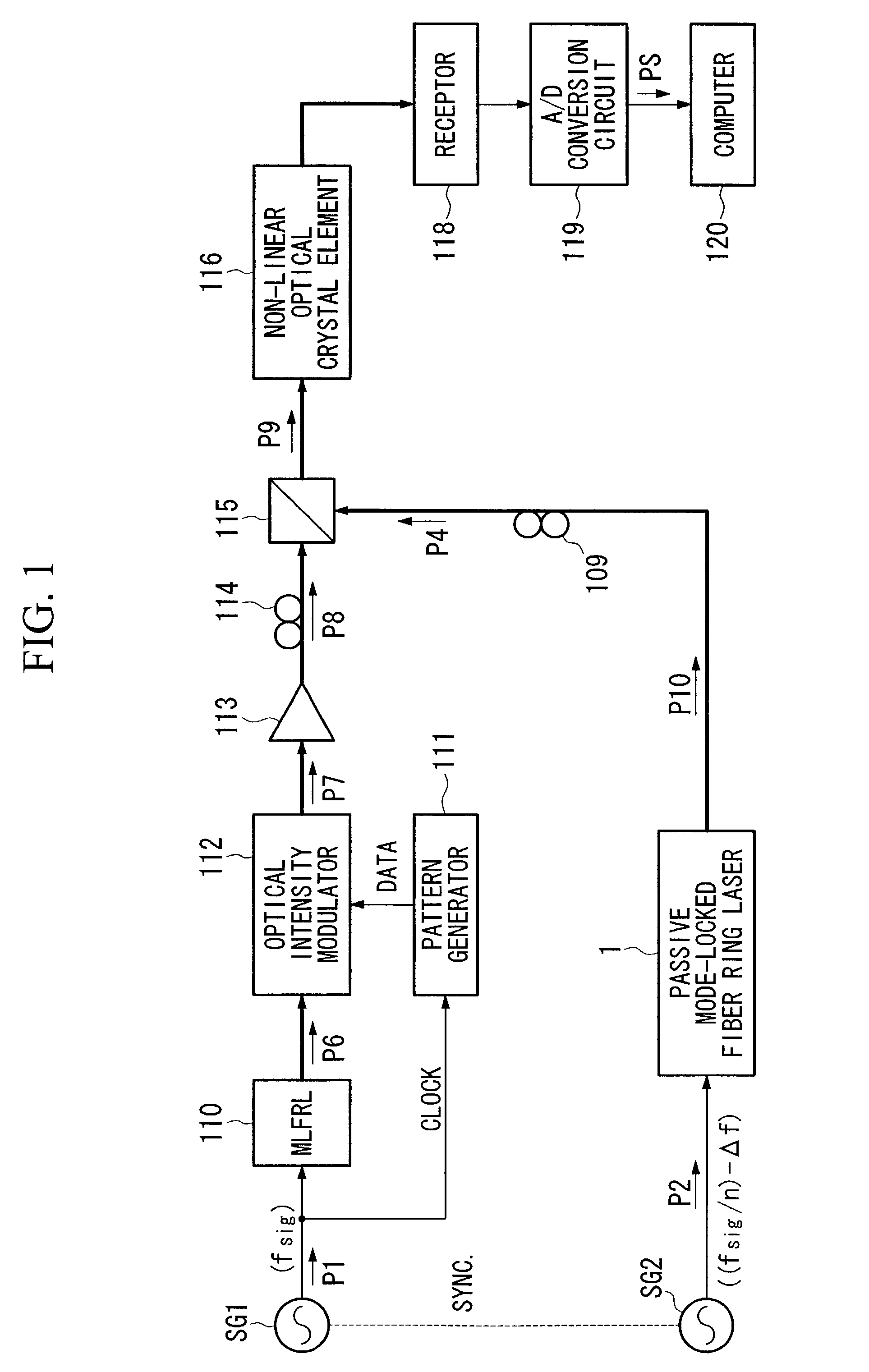
[0041]Embodiments of the present invention are explained with reference to drawings as follows. FIG. 1 is a block diagram of an optical sampling waveform measuring apparatus. FIG. 2 is a view for schematically explaining an optical sampling waveform measuring apparatus which is used in the present invention.
[0042]In FIG. 1, same reference numerals are added to same devices and signals as the case of a conventional optical sampling waveform measuring apparatus shown in FIG. 5. Particularly, a device which generates a signal light P8 to be measured is common between the present invention and the conventional apparatus.
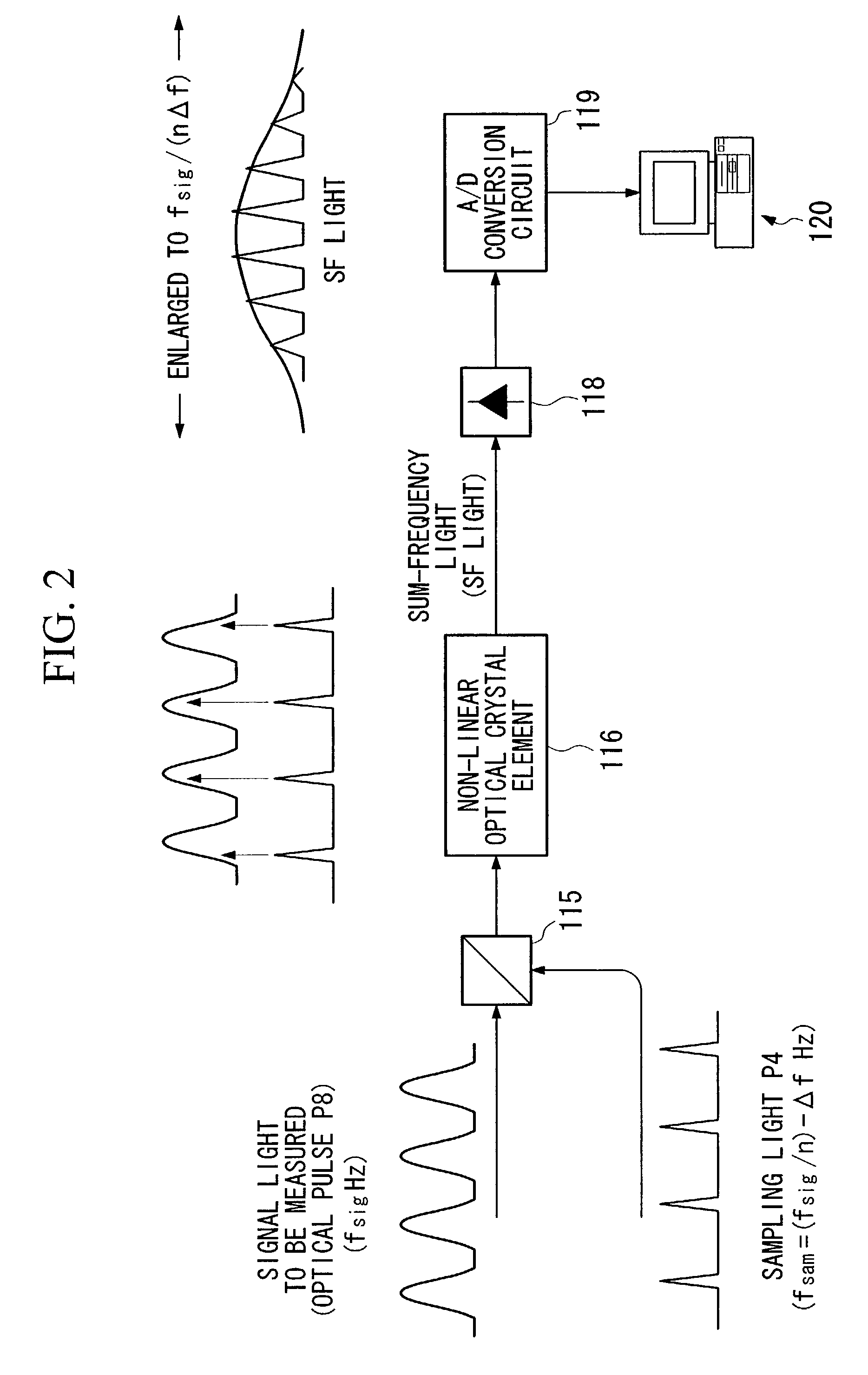
[0043]Here, a measuring theory of an optical sampling waveform measuring apparatus of the present invention is explained with reference to FIG. 2.
[0044]In FIG. 2, a signal light (optical pulse P8) to be measured having a cycle frequency “fsig” and a sampling optical pulse P4 having a cycle frequency “(fsig / n)−Δf” (n is an integral number) which is several hundreds of Hz ...
second embodiment
[0110]That is, in the second embodiment, a sampling reference signal P2 which is supplied to a passive mode-locked fiber ring laser 1 is generated by performing 1 / n frequency division to a cycle frequency fsig of a signal light P1 to be measured for exciting a source of signal to be measured and giving a delay sweeping frequency difference Δf by a PLL 51.
[0111]By doing this way, it is possible to handle a signal light to be measured having any cycle frequency by varying a frequency division ratio “n” of a 1 / n frequency divider 50. Also, it is possible to perform a frequency division automatically by varying a frequency division ratio “n” which divides a cycle frequency fsig of a signal P1 to be measured by a computer 120.
[0112]Also, a second embodiment of an optical sampling waveform measuring apparatus has the same effects as those of the first embodiment.
PUM
 Abstract
Description
Claims
Application Information