Optical head and optical disk apparatus

a technology of optical disk and head, applied in the direction of heads, instruments, data recording, etc., can solve the problems of affecting recording and reproducing signals, affecting the thickness and tilt of disk substrates, and complicated mechanism systems and control systems, so as to achieve low cost and increase speed

Inactive Publication Date: 2006-06-27
HITACHI CONSUMER ELECTRONICS CORP
View PDF11 Cites 4 Cited by
  • Summary
  • Abstract
  • Description
  • Claims
  • Application Information

AI Technical Summary

Benefits of technology

[0009]The present invention has been made in view of drawbacks in the aforementioned prior art. It is an object of the present invention to provide an optical head, in which a high NA objective lens is incorporated, and which is suitable for increasing a speed at low costs, and to provide an optical disk apparatus incorporating the same.
[0011]According to the present invention, when the spherical aberration is corrected, since the coma aberration generated by offset of the objective lens decreases, the double servo becomes unnecessary. Therefore, it is possible to realize the high density optical head suitable for an increase in speed at low costs.
[0018]If a light detector having a constitution, in which a plurality of light-receiving regions are formed on one substrate, the reproducing signal is detected by the zero-order diffraction light of the detected light dividing device, and the focal shift signal and tracking shift signal are detected by the ± first-order diffraction light as described above, is used as a light detector, it becomes possible to relatively reduce noises of the reproducing signal. In addition, the number of optical light-receiving devices requiring an adjustment becomes only one, and thus it becomes possible to suppress manufacturing costs.

Problems solved by technology

At this time, there is a problem that, the more the NA increases, the more an aberration generated due to a positional shift of an optical system, error of thickness and tilt of a disk substrate, or the like increases.
However, in the case where the correction amount is relatively large as when the spherical aberration equivalent to an interlayer interval is corrected in recording and reproducing to and from two-layer disk, the coma aberration by this offset is affected largely, and a spot is deteriorated by the tracking operation, whereby the recording and reproducing of signals are adversely affected.
However, since the optical head itself is moved in the double servo system, a mechanism system and a control system become complicated, and costs increase.
Furthermore, since a movable part is large, this system is unfit for an increase in speed.

Method used


Image

  • Optical head and optical disk apparatus
  • Optical head and optical disk apparatus
  • Optical head and optical disk apparatus

Examples


Embodiment Construction

[0040]Hereinafter, embodiments of the present invention will be described with reference to the drawings.

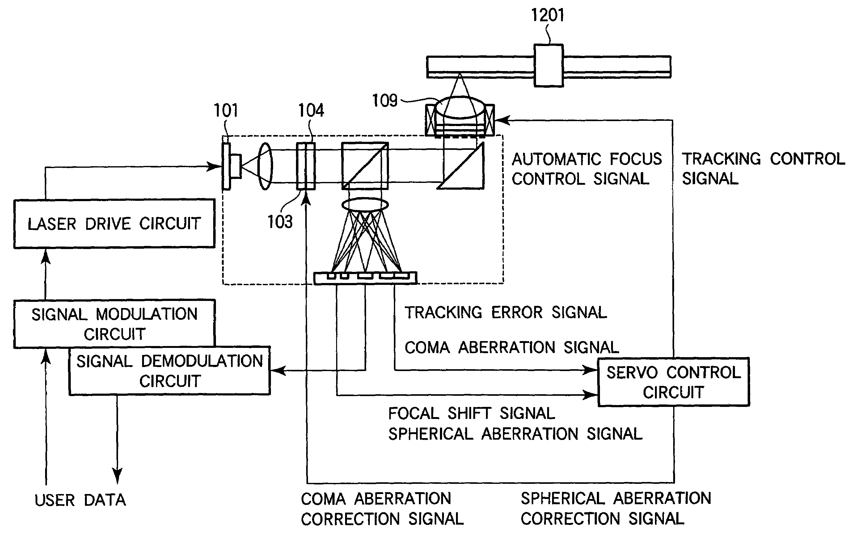
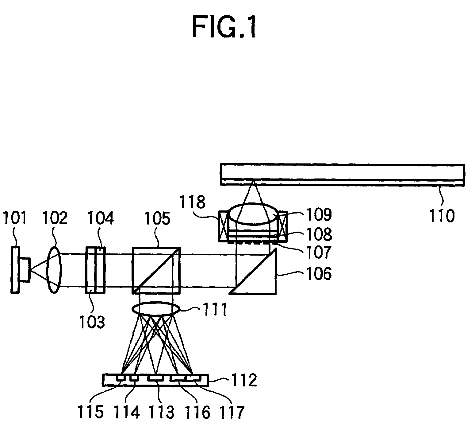
[0041]FIG. 1 is a schematic view showing one example of an optical system of an optical head according to the present invention. Laser beam emitted from a blue-violet semiconductor laser 101 of a wavelength of 400 nm is collimated to a substantially parallel beam by a collimator lens 102. The beam passed through a polarizing beam splitter 105 is reflected upward toward an optical disk medium 110 by a raising mirror 106, and become substantially circularly polarized light by a λ / 4 wavelength plate 108, and are condensed on an information recording surface of the optical disk medium 110 by an objective lens 109 (NA 0.85, optimal substrate thickness 0.1 mm). The reflected light from the information recording surface is returned to the objective lens 109 again, and becomes linearly polarized light perpendicular to a polarizing direction at the incident time by the λ / 4 wavelength plat...


PUM

PropertyMeasurementUnit
diameteraaaaaaaaaa
wavelengthaaaaaaaaaa
thicknessaaaaaaaaaa

Abstract

To stably carry out recording and reproducing to and from a high density optical disk without using a double servo in the optical disk using a high NA objective lens. A detection of a spherical aberration and a detection of a coma aberration in a radial direction are simultaneously performed, and the coma aberration generated with the offset of an objective lens 109 is corrected in real time, thus enlarging an allowable offset amount of the objective lens. In order to simultaneously detect the spherical aberration and the coma aberration, focal shift and tracking shift signals in an inside region and outside region of reflected light flux are detected respectively, and the differential signals are set as spherical aberration and coma aberration signals.

Description

[0001]The present application is a continuation of application Ser. No. 09 / 921,142, filed Aug. 3, 2001 now U.S. Pat. No. 6,807,133, the contents of which is incorporated herein by reference.BACKGROUND OF THE INVENTION[0002]The present invention relates to an optical disk apparatus, which records and reproduces information by use of laser beam, and to an optical head incorporated in the optical disk apparatus.[0003]As a recording machine prevalent currently, a recording machine utilizing a videotape is in popular use. However, a recording machine utilizing an optical disk has been commercially available. The optical disk is more superior to the videotape in random access performance. From viewpoints of a easiness to handle, a repetitive reproduction, a fact that an image deterioration scarcely occurs due to change over time, compactness, or the like, it is considered that the recording machine using the optical disk will widely spread in the future. Furthermore, in addition to the re...

Claims


Application Information

Patent Timeline
Patent Type & Authority Patents(United States)
IPC IPC(8): G11B7/00G11B7/095G11B7/09G11B7/13G11B7/135
CPCG11B7/0943G11B7/0948G11B7/123G11B7/1353G11B7/1369G11B7/13927G11B7/131G11B7/0956G11B2007/0013
Inventor ARIYOSHI, TETSUOUMEDA, MARIKOSHIMANO, TAKESHI
Owner HITACHI CONSUMER ELECTRONICS CORP
Why Eureka
Try Eureka