Microphone array diffracting structure

a technology of microphone arrays and arrays, applied in the direction of electrical transducers, piezoelectric/electrostrictive transducers, transducer types, etc., can solve the problems of unsuitability for physical small arrays, unwieldy systems, and large array designs, so as to increase the effective aperture size and directionality of microphone arrays

Inactive Publication Date: 2006-06-27
NAT RES COUNCIL OF CANADA
View PDF8 Cites 37 Cited by
  • Summary
  • Abstract
  • Description
  • Claims
  • Application Information

AI Technical Summary

Benefits of technology

[0013]The present invention uses diffractive effects to increase the effective aperture size and the directionality of a microphone array along with a signal processing method which generates time delay weights, amplitude and phase delay adjustments for signals coming from different microphones in the array.

Problems solved by technology

While superdirective approaches do work, the resulting array designs can be very sensitive to the effects of microphone self noise and errors in matching microphone amplitude and phase responses.
Unfortunately, the system described is unwieldy.
These requirements render Elko unsuitable for applications requiring physically small arrays.
However, Bartlett does not achieve the desired directivity required in some applications.
While Bartlett would be useful as a microphone in a cellular telephone handset, it cannot be readily adapted for applications such as handsfree telephony or teleconferencing in which high directionality is desirable.
While Kuhn may produce the desired directionality, it is clear that Kuhn is quite complex and impractical for the uses envisioned above.
Elko et al however, utilizes costly signal processing means to reduce noise.
The signal processing capabilities required to keep adaptively calculating the required real-time analysis can be prohibitive.
The directional microphones, however, do not allow for a changing directionality as to the source of the sound.

Method used


Image

  • Microphone array diffracting structure
  • Microphone array diffracting structure
  • Microphone array diffracting structure

Examples


Embodiment Construction

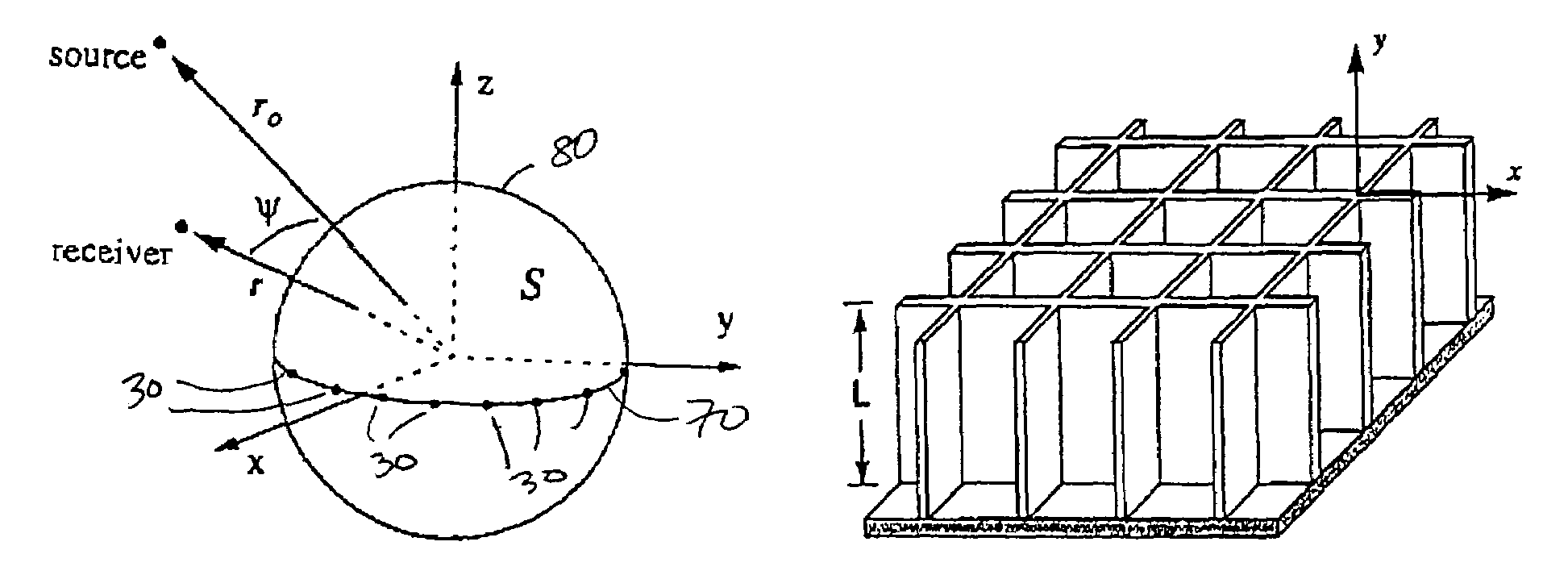
[0037]To analyse the effect of introducing a diffracting structure in a microphone array, some background on array signal processing is required.

[0038]In a microphone array the separate signals from the separate microphones are weighted and summed with a processor to provide an output signal. This process is represented by the equation:

[0039]V∝∑m=1M⁢⁢wm⁢pm

where V is the electrical output signal;[0040]wm is the weight assigned to the particular microphones;[0041]M is the number of microphones; and[0042]pm is the acoustic pressure signal from a microphone.

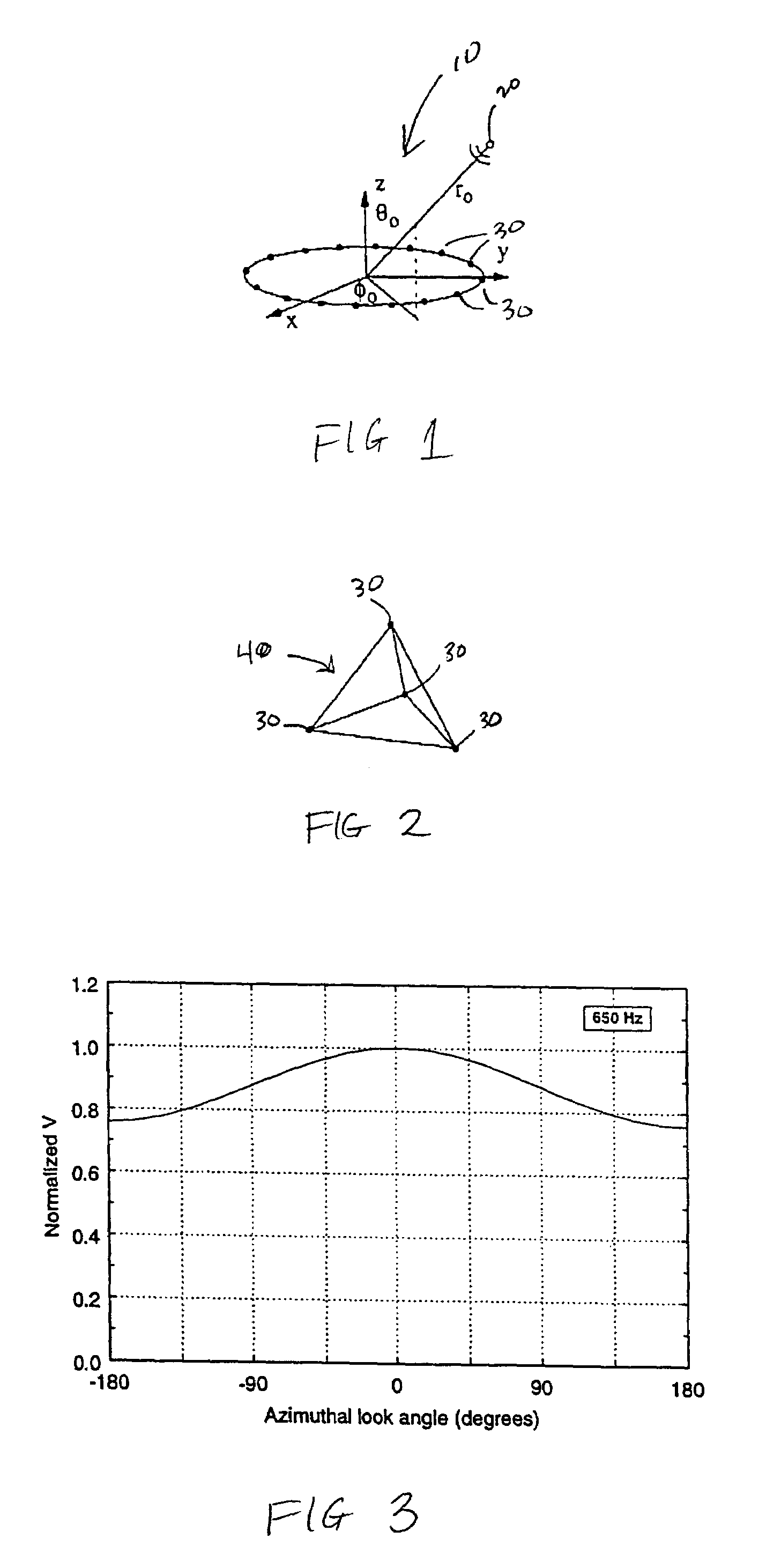
[0043]The weights are complex and contain both an amplitude weighting and an effective time delay τm, according to

wm=|wm|e(+iωτm)

where ω is the angular sound frequency. An e(−iwt) time dependence is being assumed. Both amplitude weights and time delays are, in general, frequency dependent.

[0044]Useful beampatterns can be obtained by using a uniform weighting scheme, setting |wm|=1 and choosing the time delay τm so that all microphon...


PUM


Abstract

The present invention increases the aperture size of a microphone array by introducing a diffracting structure into the interior of a microphone array. The diffracting structure within the array modifies both the amplitude and phase of the acoustic signal reaching the microphones. The diffracting structure increases acoustic shadowing along with the signal's travel time around the structure. The diffracting structure in the array effectively increases the aperture size of the array and thereby increases the directivity of the array. Constructing the surface of the diffracting structure such that surface waves can form over the surface further increases the travel time and modifies the amplitude of the acoustical signal thereby allowing a larger effective aperture for the array.

Description

[0001]This application claims the benefit of Provisional Application No. 60 / 112,950, filed Dec. 18, 1998.FIELD OF THE INVENTION[0002]The present invention relates to microphone technology and specifically to microphone arrays which can achieve enhanced acoustic directionality by a combination of both physical and signal processing means.BACKGROUND OF THE INVENTION[0003]Microphone arrays are well known in the field of acoustics. By combining the outputs of several microphones in an array electronically, a directional sound pickup pattern can be achieved. This means that sound arriving from a small range of directions is emphasized while sound coming from other directions is attenuated. Such a capability is useful in areas such as telephony, teleconferencing, video conferencing, hearing aids, and the detection of sound sources outdoors. However, practical considerations mitigate against physically large arrays. It is therefore desirable to obtain as much acoustical directionality out ...

Claims


Application Information

Patent Timeline
Patent Type & Authority Patents(United States)
IPC IPC(8): H04R25/00
CPCH04R1/406H04R2430/20H04R25/407H04R25/405
Inventor STINSON, MICHAEL R.RYAN, JAMES G.
Owner NAT RES COUNCIL OF CANADA
Why Eureka
Try Eureka