Correcting misalignment between data and a carrier signal in transmitters

a transmitter and data technology, applied in the field of communication equipment, can solve the problems of distorted pulses not having the correct soliton waveform required, difficult to maintain synchronization, and poorly controlled phase drift, etc., and achieve the effect of reducing misalignmen

Active Publication Date: 2006-06-27
WSOU INVESTMENTS LLC +1
View PDF12 Cites 20 Cited by
  • Summary
  • Abstract
  • Description
  • Claims
  • Application Information

AI Technical Summary

Benefits of technology

[0010]According to another embodiment, the present invention is a method of reducing misalignment between a carrier signal and a data signal, comprising the steps of: (i) analyzing a data-modulated signal corresponding to the carrier and data signals; and (ii) introducing a phase shift between the data signal and a clock signal based on the analysis, wherein the carrier signal is based on the clock signal.

Problems solved by technology

One problem with system 100 is that it requires synchronizing optical carrier signal 118 and electronic data stream 102.
Such synchronization is difficult to maintain due to often occurring and, in general, poorly controllable phase drifts in E / O modulators.
Distorted pulses do not have the correct soliton waveform required for propagation through a long-haul optical fiber.
In addition, misalignment may result in the transmission of portions of carrier-signal pulses that ideally should not be transmitted.
Both of these effects may result in increased bit error rates at a receiver.

Method used


Image

  • Correcting misalignment between data and a carrier signal in transmitters
  • Correcting misalignment between data and a carrier signal in transmitters
  • Correcting misalignment between data and a carrier signal in transmitters

Examples


Embodiment Construction

[0021]Reference herein to “one embodiment” or “an embodiment” means that a particular feature, structure, or characteristic described in connection with the embodiment can be included in at least one embodiment of the invention. The appearances of the phrase “in one embodiment” in various places in the specification are not necessarily all referring to the same embodiment, nor are separate or alternative embodiments mutually exclusive of other embodiments. Although the invention is particularly suitable for use with communications equipment, those skilled in the art can appreciate that the invention can be equally applied to other types of electrical and / or optical equipment.

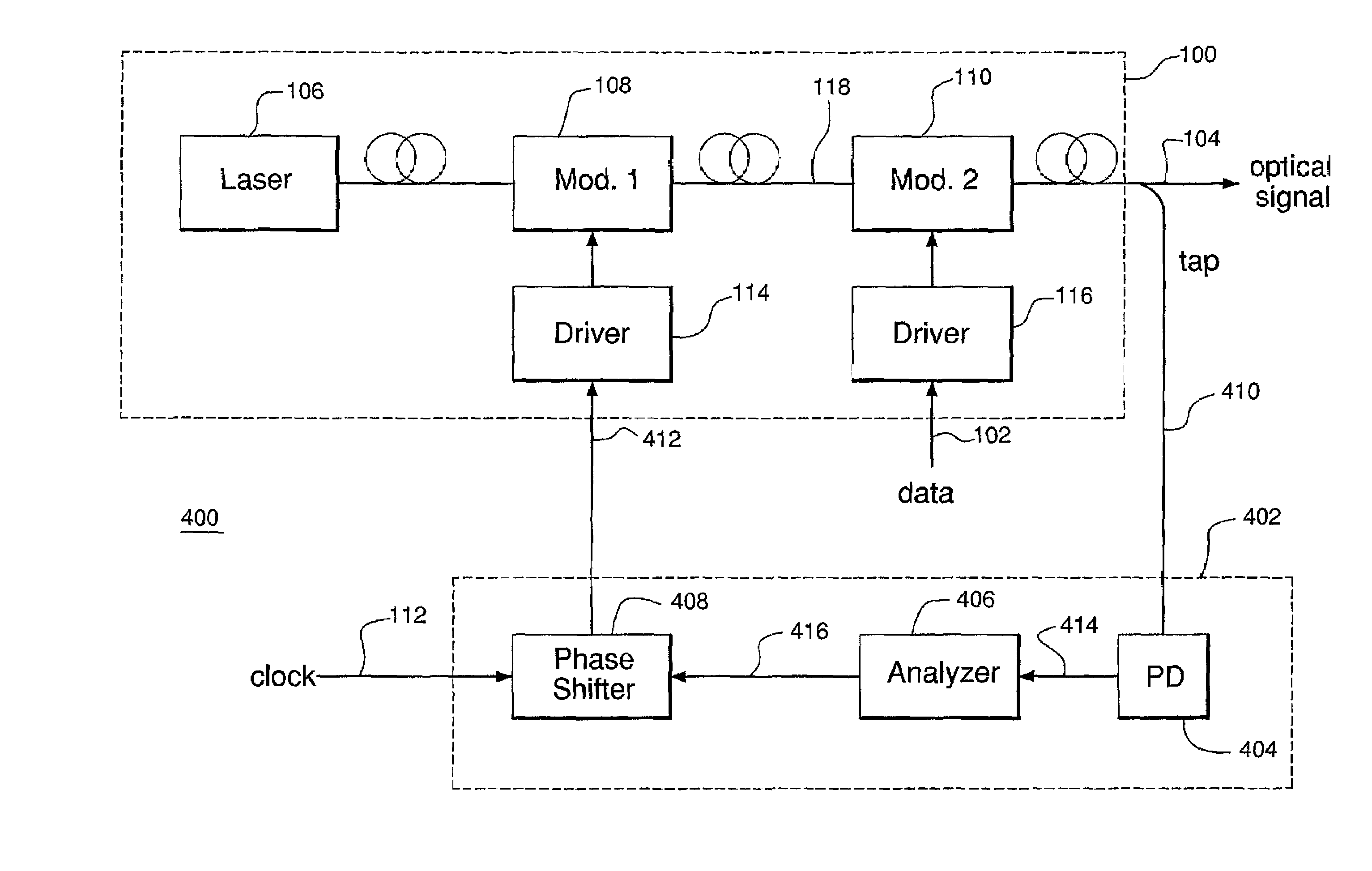
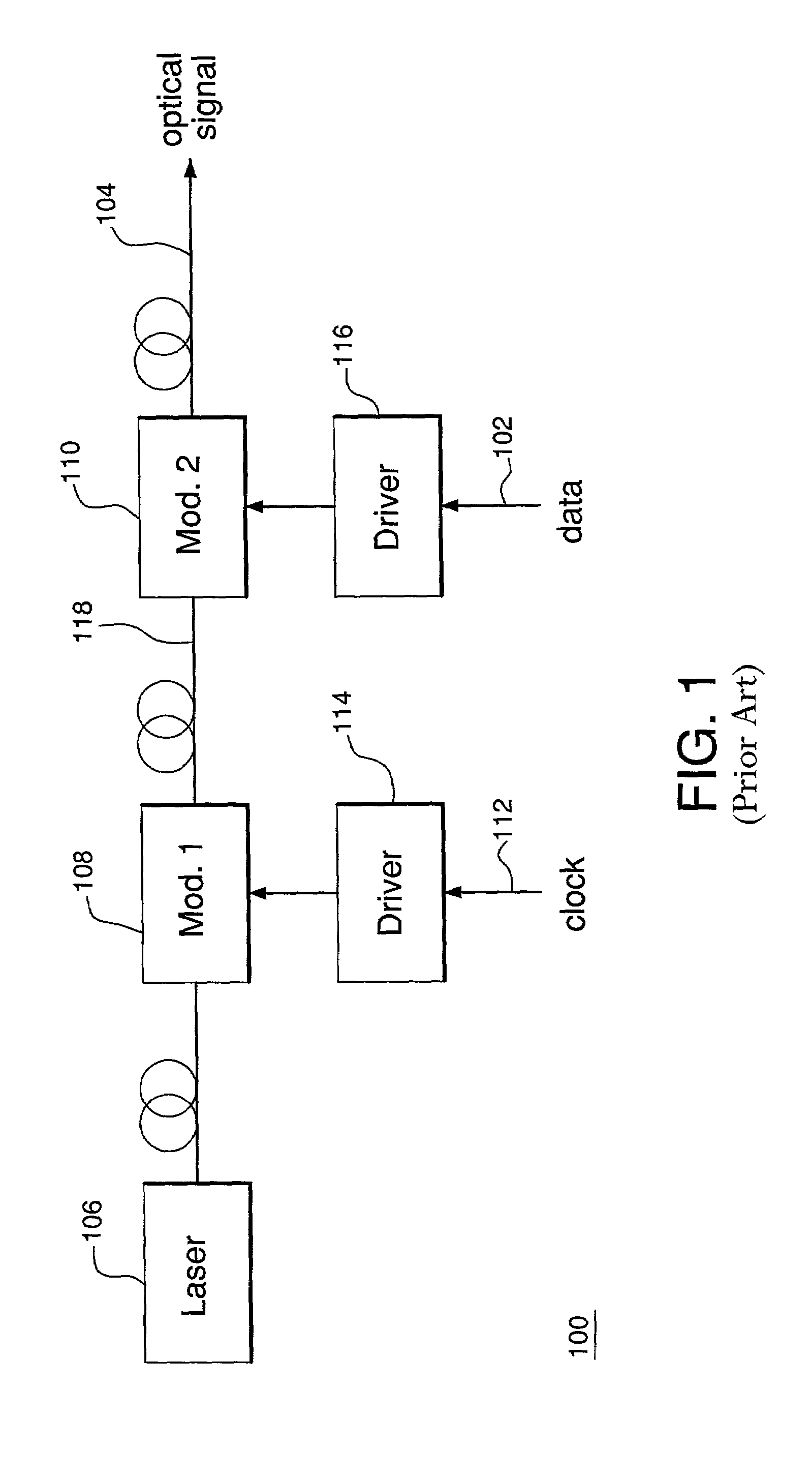
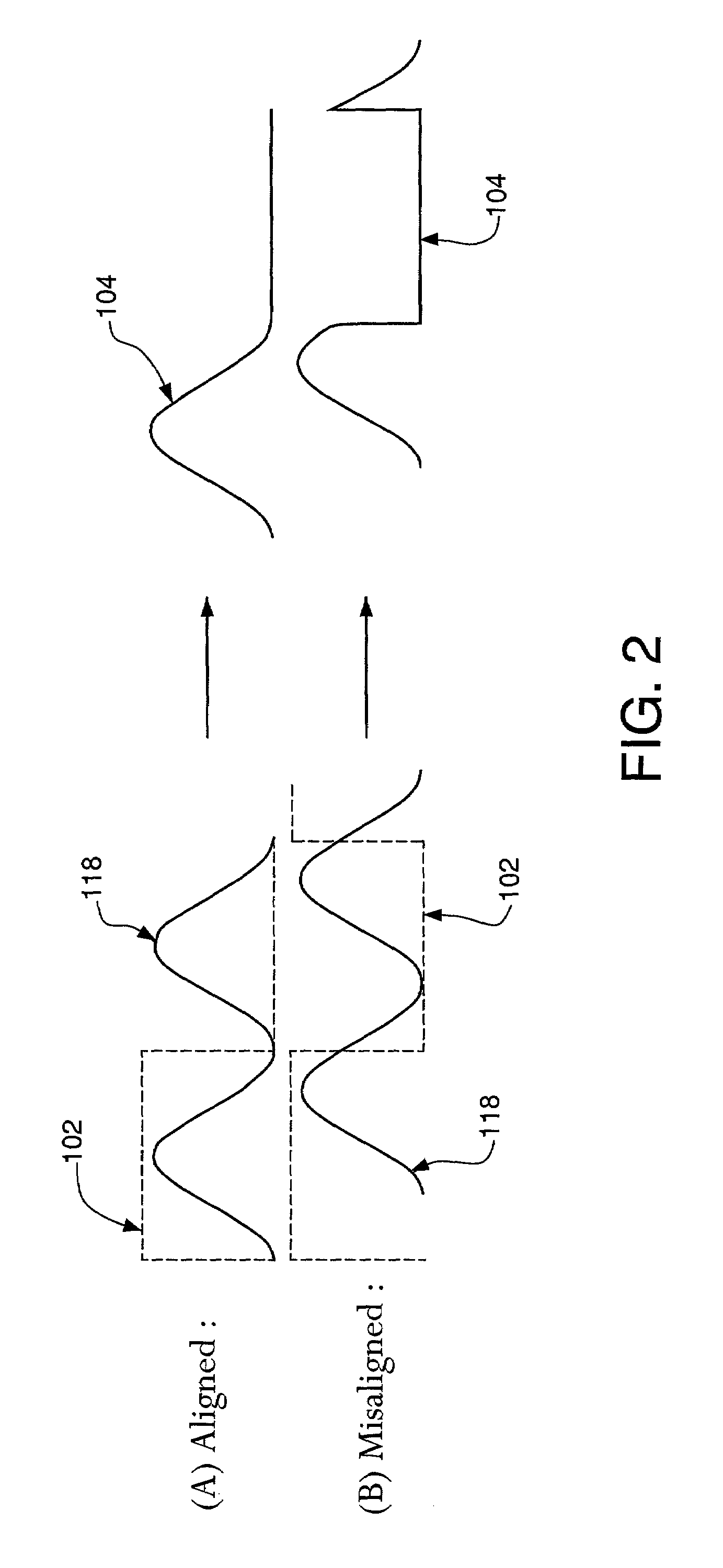
[0022]Before embodiments of the present invention are described in detail, spectral properties of modulated optical signals, such as signal 104 of system 100, are briefly characterized.

[0023]FIGS. 3A and 3B show two representative spectra of a data-modulated optical signal produced using an optical pulse train o...


PUM


Abstract

A device and technique for aligning an optical carrier signal (e.g., a soliton pulse train) with a data signal in a transmitter. According to the invention, the device is configured to analyze the radio frequency (RF) spectrum of the transmitter's output. In one implementation, the device evaluates the amount of energy in a certain frequency band located near a selected null of the RF spectrum. In another implementation, the device examines the shape of the RF spectrum within that frequency band. In either case, based on the analysis, the device adjusts the phase of the clock signal driving an electro-optic (E/O) modulator in the transmitter. Such adjustment reduces misalignment between the optical carrier signal and data resulting, e.g., from thermal effects in the E/O modulator. The device may be used, e.g., in long-haul optical transmission systems operating at 10 GBit/s.

Description

BACKGROUND OF THE INVENTION[0001]1. Field of the Invention[0002]The present invention relates to communication equipment.[0003]2. Description of the Related Art[0004]Transmission of optical signals through fiber-optic networks is widely used in modern communication systems. In particular, long-haul, high data-rate wavelength division multiplexed (WDM) optical transmission is an important component of optical networking. One known way to accomplish long-haul transmission is by using soliton optical pulses. Due to special non-linear optical characteristics, a soliton pulse is less susceptible to chromatic and polarization mode dispersion than, e.g., a rectangular pulse. As such, soliton pulses can provide relatively low bit error rates and therefore high reliability for optical transmission.[0005]FIG. 1 shows a typical prior art system 100 for transmitting data using soliton pulses. System 100 is configured to convert an electronic data stream 102 into an optical signal 104. System 10...

Claims


Application Information

Patent Timeline
Patent Type & Authority Patents(United States)
IPC IPC(8): H04B10/04H04B10/155
CPCH04B10/505H04B10/50577H04B10/5057H04B10/5051
Inventor SINSKY, JEFFREY H.
Owner WSOU INVESTMENTS LLC
Why Eureka
Try Eureka