Distributed power train (DGD) with multiple power paths

a power train and power path technology, applied in the direction of gearing details, machines/engines, gearing, etc., can solve the problems of single generator system losing all of its capacity, lowering its size and cost, and reducing the size and cost of single generator system, so as to improve the gear arrangement and reduce the manufacturing cost. , the effect of cost saving

Inactive Publication Date: 2006-07-04
UNITED TECH CORP
View PDF5 Cites 43 Cited by
  • Summary
  • Abstract
  • Description
  • Claims
  • Application Information

AI Technical Summary

Benefits of technology

[0019]The invention has the advantage that the novel arrangement of the gears, creating multiple power paths, lowers manufacturing cost. This is because the invention uses only external gears, resulting in a cost savings, since external gears are more easily produced and more readily obtained, particularly when the quality desired demands ground teeth.
[0020]The invention has the further advantage that by using a double helical input pinion gear, the economy of wide-face gears with smaller diameters is achieved. Double-helical teeth allow wide faces while reducing manufacturing tolerance requirements and have less deflection sensitivity by a factor of 2. This improvement results because each face of the double helical system acts independently for load distribution.
[0021]The invention has the further advantage that because the gearing configuration provides large step-up gear ratios in just two steps a rotational device runs at higher speed, lowering its size and cost.

Problems solved by technology

The size of the components necessitates very large lifting equipment, making both the land-based cranes and ocean lifting equipment extremely costly.
A single generator system loses all of its capacity when the generator experiences a fault.
A high gear ratio causes a generator to run at higher speed, lowering its size and cost.
This results in undesirable maintenance and disposal of hazardous materials.
Gear noise is very objectionable in wind turbines, leading to use of isolators to mount transmissions to wind turbine frames.
These isolators contain rubber elements and have a finite fatigue life.
They are in the load path of a highly loaded system and are therefore difficult to replace.

Method used


Image

  • Distributed power train (DGD) with multiple power paths
  • Distributed power train (DGD) with multiple power paths
  • Distributed power train (DGD) with multiple power paths

Examples


Embodiment Construction

[0027]In this specification the terms “gear” and “pinion” refer to machine components consisting of a wheel attached to a rotating shaft that operate in pairs to transmit and modify rotary motion and torque (turning force) without slip. A gear may or may not have gear teeth.

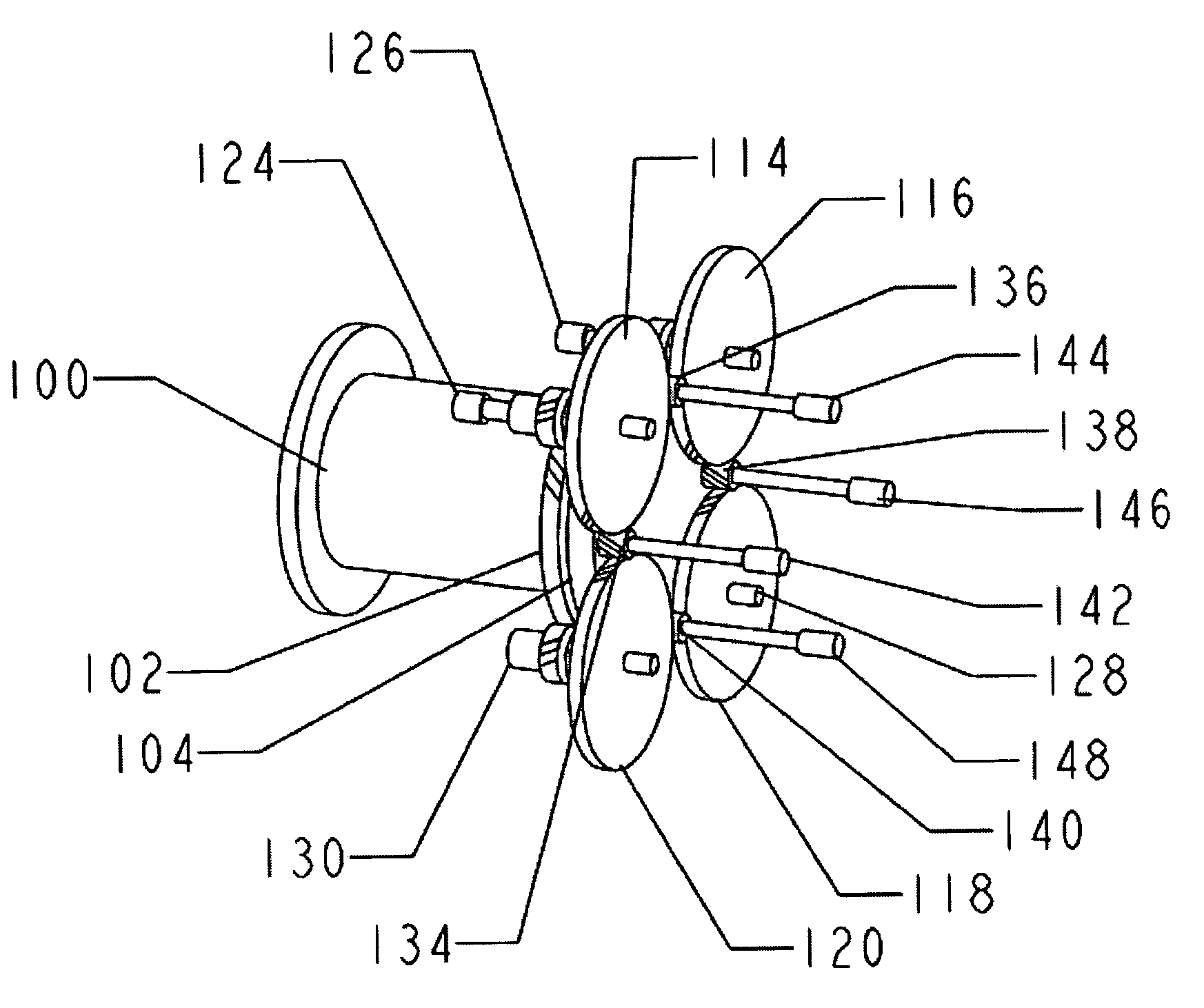
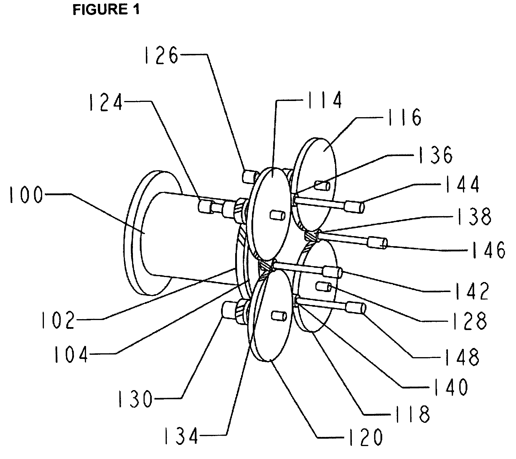
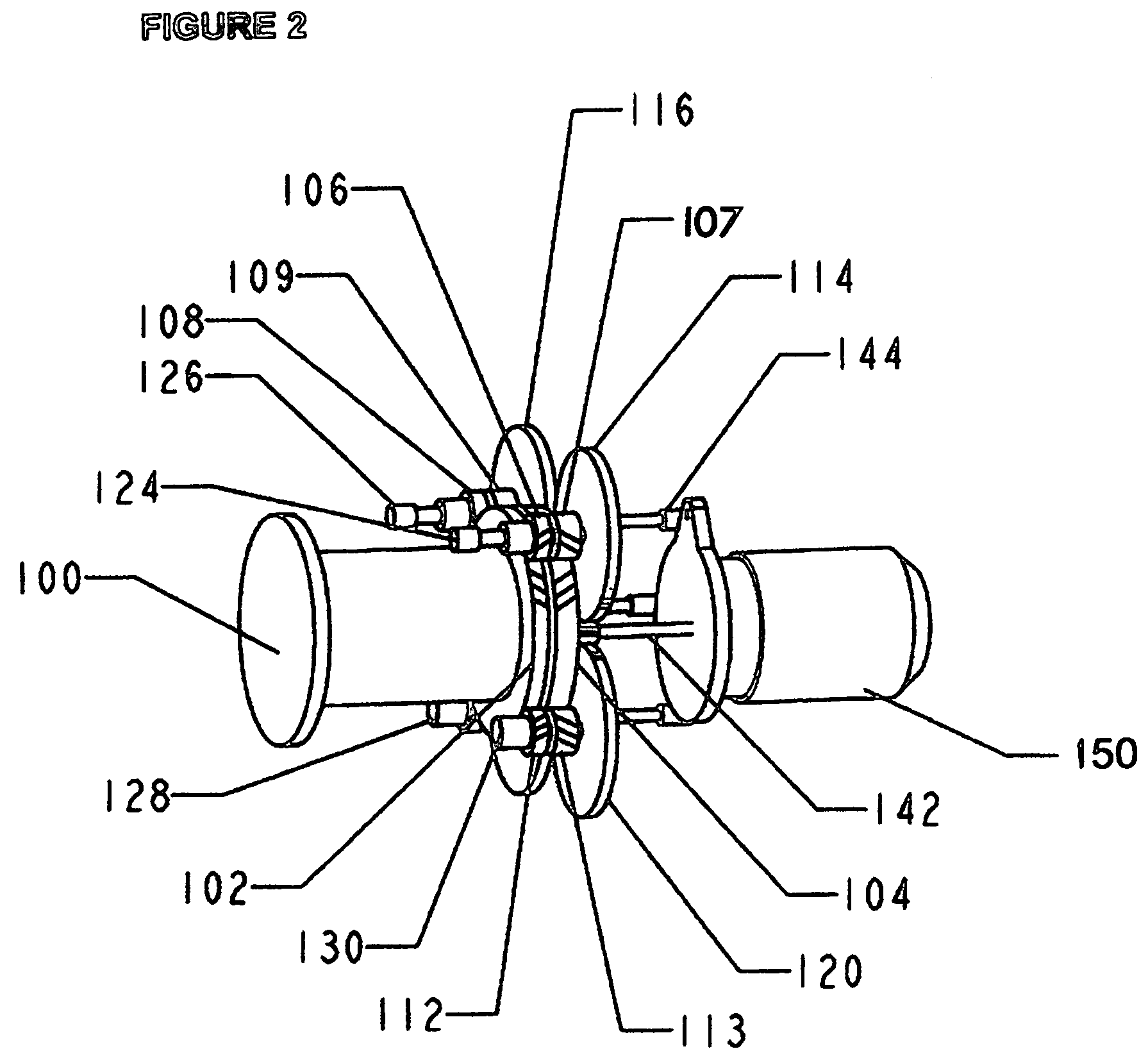
[0028]The invention shown in FIGS. 1–3 is an electric power-generating device that converts a source of energy to electricity. A main shaft 100 is capable of being turned by the source of energy. A pair of bull gears, 102, 104 is located on the main shaft. A number of intermediate gears 114, 116, 118, 120 are located around a perimeter of the bull gears. Intermediate gear 114 is connected to an input shaft 124 having a double helix pinion 106, 107, that engages the pair of bull gears 102, 104. The other intermediate gears 116, 118, 120, are similarly connected to respective input shafts having double helix pinions that engage the pair of bull gears. A plurality of output shafts 142, 144, 146, 148 are provided. Ou...


PUM


Abstract

An electric power-generating device with a rotor turned by an external source of energy, such as wind or water currents. The rotor is coupled to a main shaft. A pair of bull gears is located on the main shaft. A number of intermediate gears are located around a perimeter of the bull gears. An intermediate gear is connected to an input shaft having a double helix pinion that engages the pair of bull gears. The other intermediate gears are similarly connected to respective input shafts having double helix pimons that engage the pair of bull gears. A plurality of output shafts is provided. An output shaft has a single-helix output pinion that engages two adjacent intermediate gears. The other output shafts are similarly connected to respective adjacent intermediate gears. A number of rotational devices are connected to the output shafts.

Description

BACKGROUND OF THE INVENTION[0001]1. Field of the Invention[0002]This invention relates to multi-stage gearing apparatus and more particularly to an apparatus for distributing a source of energy to multiple rotational devices.[0003]2. Description of the Prior Art[0004]U.S. Pat. No. 6,304,002, granted on Oct. 16, 2001, describes a power train for an electric power-generating device in which wind or water currents turn a rotor. A torque-dividing gearbox is coupled to an input shaft driven by the rotor. The torque-dividing gearbox has a plurality of output shafts located around a perimeter of the input shaft. A number of torque-reducing gearboxes are each coupled to a respective one of the output shafts, each one of the torque-reducing gearboxes driving a generator. In one design the torque-reducing gearboxes and generators are held stationary and the torque-dividing gearbox includes a bull gear turned by the input shaft. Each one of the output shafts is connected to a gear that engages...

Claims


Application Information

Patent Timeline
Patent Type & Authority Patents(United States)
IPC IPC(8): F16H57/00F03D11/02F16H1/22
CPCF03D11/02F16H1/22F05B2210/16F05B2240/40Y10T74/19098Y02E10/722Y10T74/19628F05B2260/4031F03D15/00F03D15/10Y02E10/72
Inventor MIKHAIL, AMIR S.HAHLBECK, EDWIN C.
Owner UNITED TECH CORP
Why Eureka
Try Eureka