

Field emission display and methods of forming a field emission display
a field emission display and field emission technology, applied in the manufacture of electrode systems, electric discharge tubes/lamps, paper/cardboard articles, etc., can solve the problems of further reducing the tolerance of borosilicate glass and sodalime glass
- Summary
- Abstract
- Description
- Claims
- Application Information
AI Technical Summary
Benefits of technology
Problems solved by technology
Method used
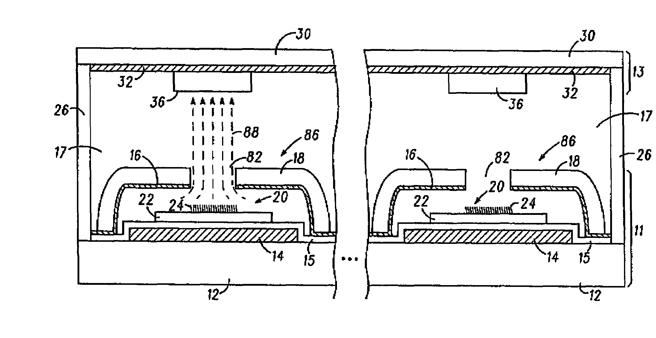
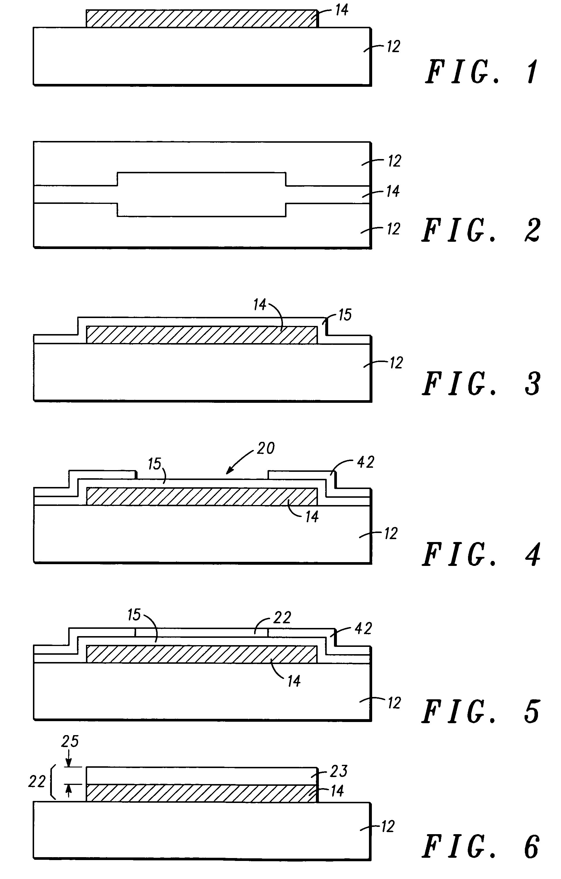
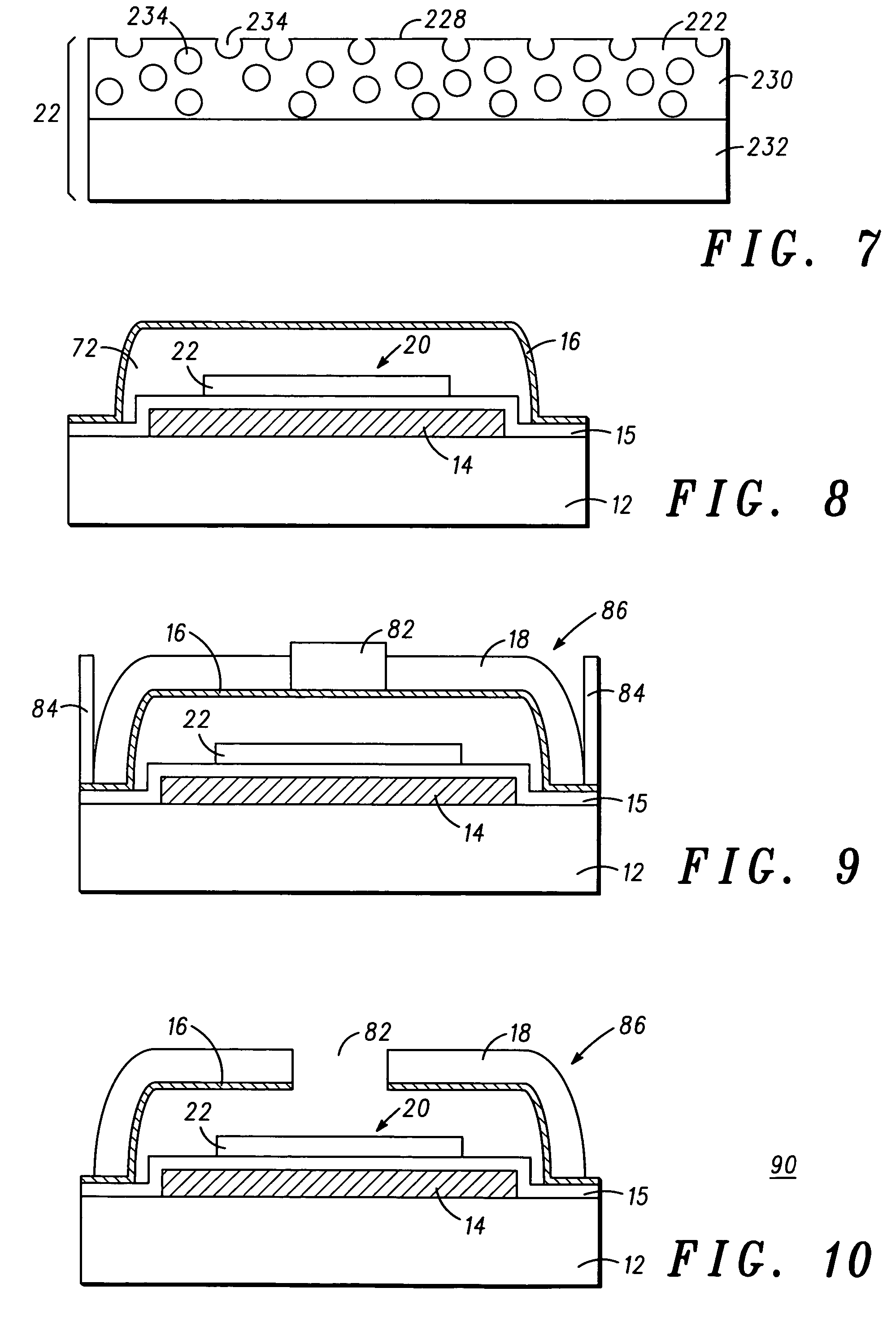
Image

Examples
example i
[0064]1. Immerse a borosilicate glass with a copper (Cu) metal pattern (i.e., substrate with an electrode) into a solution of 1×10⁻²M Al(NO3)3 in isopropyl alcohol (IPA) and apply a negative twenty volt (−20V) bias to the copper metal pattern while keeping a counter electrode, which can be constructed out of stainless steel, at ground for a duration of one (1) minute. The desired chemical reactions involved in this step are:
[0065]Al(NO3)3→Al(NO3)2++NO3− occurring in the solution;
[0066]Al(NO3)2++3OH−→Al(OH)3+2NO3− occurring at the electrode; and
[0067]Al(OH)3 is the solid partial nano-supported catalyst that is forming at the electrode.
[0068]2. Dry the borosilicate glass with the copper metal pattern with the partially formed nano-supported catalyst with a fifteen (15) minute bake at eighty degrees Celsius (80° C.).
[0069]3. Immerse the borosilicate glass with the copper metal pattern with the partially formed nano-supported catalyst into a solution of 1×10⁻³ Fe(NO3)3·9H2O M (iron(III)...
example ii
[0076]1. Immerse a borosilicate glass with a copper (Cu) metal pattern (substrate with an electrode) into a solution with 1×10⁻²M Mg(NO3)2 in isopropyl alcohol (IPA) and apply negative twenty volts (−20V) to the copper metal pattern while keeping a counter electrode, which can be constructed out of stainless steel, at ground for a duration of one (1) minute. The desired chemical reactions involved in this step are:
[0077]Mg(NO3)2→Mg(NO3)++NO3− occurring in the solution;
[0078]Mg(NO3)++2OH−→Mg(OH)2+NO3− occurring at the electrode; and
[0079]Mg(OH)2 is the solid partial nano-supported catalyst that is forming at the electrode.
[0080]2. Dry the borosilicate glass with the copper metal pattern having the partially formed nano-supported catalyst with a fifteen (15) minute bake at eighty degrees Celsius (80° C.).
[0081]3. Immerse the borosilicate glass with the copper metal pattern having the partially formed nano-supported catalyst into a solution of 1×10⁻³ Fe(NO3)3·9H2O M (iron(III)nitrate h...
example iii
[0087]1. Immerse a borosilicate glass with a copper metal pattern (substrate with an electrode) into a solution with 1×10⁻²M Al(NO3)3 plus 1×10⁻³ Fe(NO3)3·9H2O M in isopropyl alcohol (IPA) and apply a negative ten volt (−10V) bias to the copper metal pattern while keeping a counter electrode, which can be constructed out of stainless steel, at ground for a duration of one (1) minute. The desired chemical reactions involved in this step are:
[0088]Al(NO3)3→Al(NO3)2++NO3− and Fe(NO3)3→Fe(NO3)2++NO3−occurring in the solution;
[0089]Al(NO3)2++3OH−→Al(OH)3+2NO3−, Fe(NO3)++3OH−→Fe(OH)3+2NO3− and Fe(NO3)+2+3OH−→Fe(OH)3+NO3− occurring at the electrode; and Al(OH)3 and Fe(OH)3 are the solid nano-supported catalyst that is forming at the electrode.
[0090]2. Dry the borosilicate glass with the copper metal pattern with the formed nano-supported catalyst of Al2O3 / FeOx with a fifteen (15) minute bake at eighty degrees Celsius (80° C.).
[0091]3. Perform hot filament chemical vapor deposition (HFCVD) ...
PUM
 Abstract
Description
Claims
Application Information