
Glazing

Inactive Publication Date: 2006-07-04
GLAVERBEL SA
View PDF17 Cites 25 Cited by
  • Summary
  • Abstract
  • Description
  • Claims
  • Application Information

AI Technical Summary

Benefits of technology

[0012]Arranging for the edge compressive stress of the glass to have a value of greater than or equal to about 30 MPa and / or less than or equal to about 65 MPa may provide an advantageous level of edge compressive stress to confer desired mechanical characteristics and / or may be obtainable with certain manufacturing techniques.
[0018]Arranging the intermediate portion of the glazing to have a tensile stress averaged across the thickness of the glass of between about 0 MPa and 15 MPa may reduce the fragility of this portion of the glazing and reduce its susceptibility to breaking upon impact. In fact, it is almost inevitable for a heat treated glass to have an intermediate zone which averaged across the thickness of the glass is in tension. The intermediate zone may have a tensile stress averaged across its thickness of greater than 2 MPa, 4 MPa or 5 MPa and / or less than 10 MPa or 12 MPa.
[0020]Where the laminated glazing panel has two sheets of glass, each of these two sheets may have the defined levels of stress. This may confer suitable properties on the laminated glazing panel; it may also facilitate manufacture by allowing two similar or substantially identical glass sheets to be assembled together to form the, laminated glazing panel rather than requiring different manufacturing operation for each of the two glass sheets. In this case, the two glass sheets preferably have substantially the same thickness; alternatively, the two glass sheets may have different thicknesses. The two glass sheets may be bent individually, for example by pressing, rather than being bent as a pair.

Problems solved by technology

The individual sheets of glass in such a structure generally have a thickness of less than 3 mm so as to minimise their weight and it has been difficult or impossible to induce the desired stresses in such thin glass sheets by many conventional manufacturing techniques.
In addition to the durability and abrasion considerations for such glazings, the difficulty of providing the tempered characteristics perceived necessary with relatively thin sheets of glass has also been problematic.

Method used


Image

  • Glazing
  • Glazing

Examples


Embodiment Construction

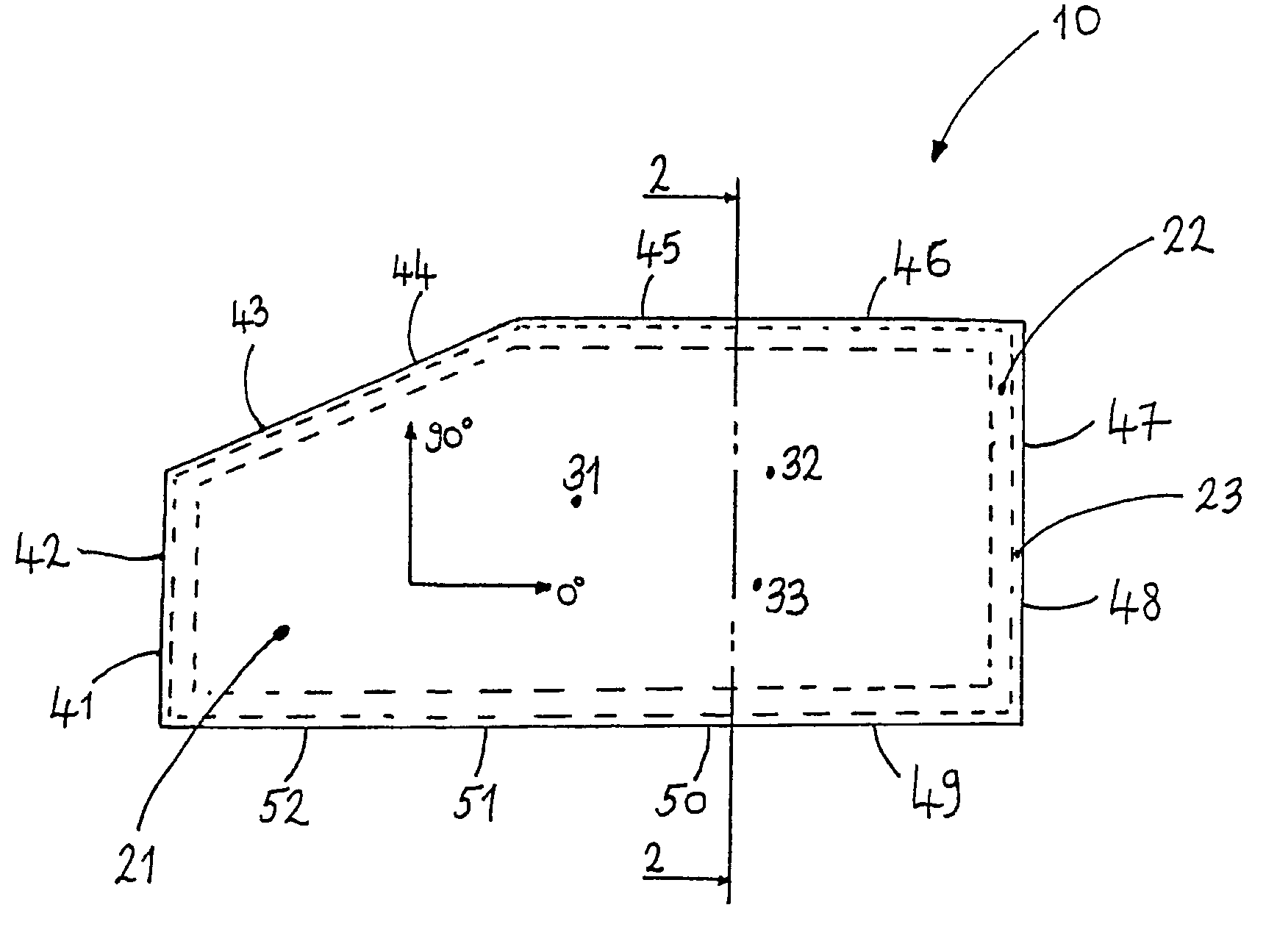
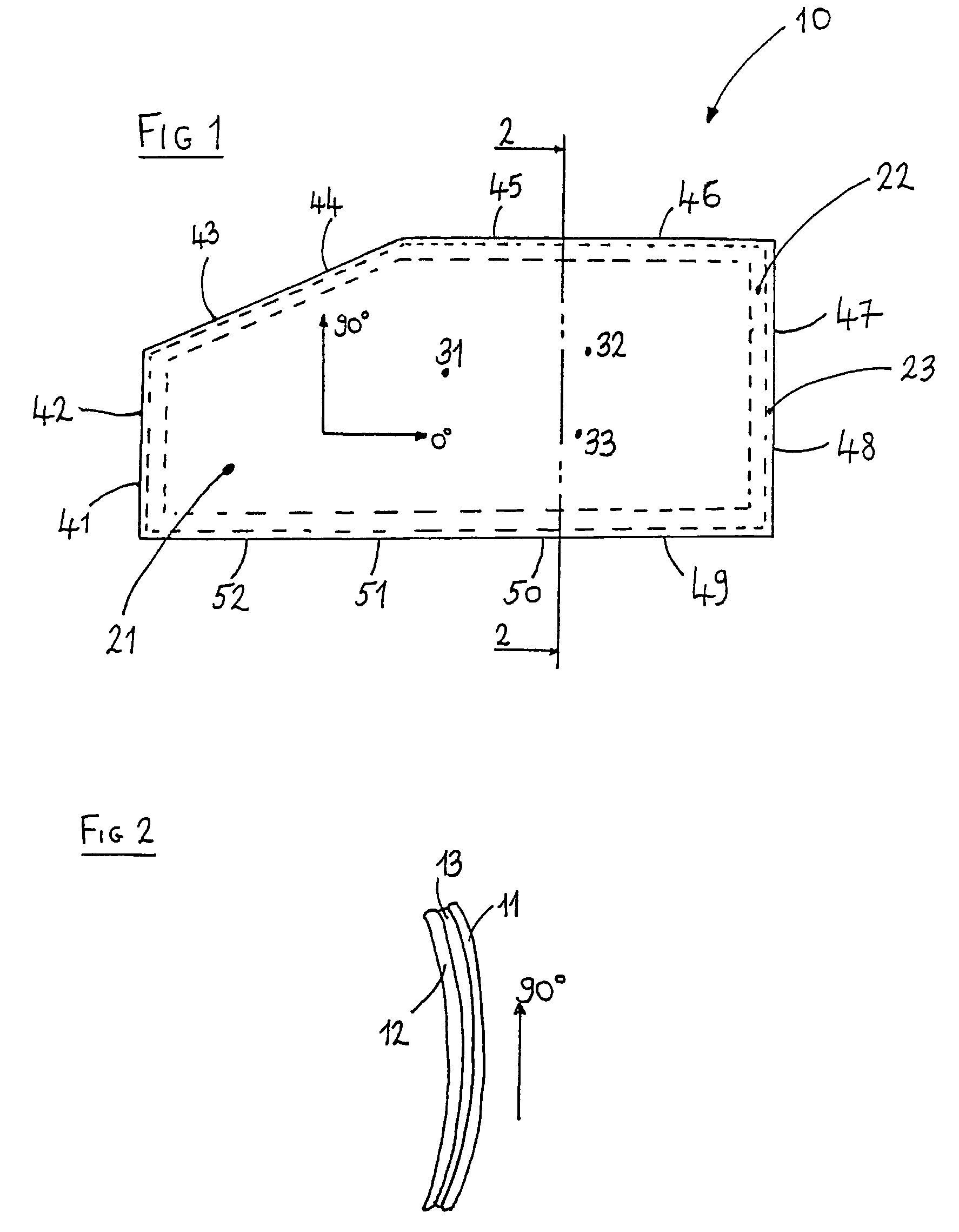
[0031]The accompanying drawings show a laminated glazing panel which forms a moveable side window of a car. The glazing 10 comprises first 11 and second 12 sheets of glass laminated together by means of a substantially transparent pvb laminating layer. It may be manufactured by cutting the desired peripheral shape of each sheet of glass from a flat, planar glass sheet to provide a blank, passing the blank through a furnace to raise its temperature sufficiently to allow it to be bent, pressing the heated blank against a convex mould to curve the blank, allowing the curved blank to cool and subsequently assembling and laminating it with a second similarly produced blank to produce a laminated glazing panel. Alternatively, a method of bending by gravity rather than by pressing may be used.

[0032]In the illustrated example, each of the glass sheets 11,12 has a thickness of 1.7 mm and has a similar stress distribution.

[0033]As indicated by the dotted lines in FIG. 1, the glass sheet may b...


PUM

PropertyMeasurementUnit
Lengthaaaaaaaaaa
Lengthaaaaaaaaaa
Thicknessaaaaaaaaaa

Abstract

A laminated glazing panel (10) has at least one sheet of glass having a thickness of between 0.8 mm and 3.5 mm. The glass sheet has: a) an edge compression stress of between 20 MPa and 90 MPa; and b) a surface compressive stress at a central portion of the glass of between 2 MPa and 39 MPa. The glazing panel may be used as a laminated automotive glazing. A method of manufacturing a laminated glazing panel is also disclosed, comprising individually bending two sheets of glass and subsequently assembling and laminating the two sheets of glass together.

Description

CROSS REFERENCE TO RELATED APPLICATIONS[0001]This application is the U.S. National Stage of International Application No. PCT / EP01 / 08335 filed 18 Jul. 2001, and claims the priority of European Application No. 00202586.4 filed 20 Jul. 2000. The entirety of each of those applications is incorporated herein by reference.BACKGROUND OF THE INVENTION[0002]This invention relates to glazing panels and particularly but not exclusively to laminated glazing panels intended for automotive side windows and rear windows.[0003]Whilst the invention will be described with particular reference to laminated automotive side windows it may also be used in other applications, for example vehicle windscreens, vehicle backlights, vehicle sunroofs, other vehicle glazing panels and other laminated glazings.[0004]Car sidelights have traditionally be provided as monolithic thermally tempered glass sheets having a thickness of between about 3 mm and 5 mm. The tempering is arranged to increase the mechanical res...

Claims


Application Information

Patent Timeline
IPC IPC(8): B32B17/06B60J1/00B32B17/10C03B27/00C03C27/12F16H55/08
CPCB32B17/10B32B17/10036B32B17/10761B32B17/10981F16H55/0873C03B27/00B32B2367/00B32B17/10005
Inventor MEERMAN, CHRISTOPHE
Owner GLAVERBEL SA
Learn More