Method and apparatus for remote measurement of vibration and properties of objects

a technology of electromagnetic wave and remote measurement, which is applied in the direction of distance measurement, instruments, specific gravity measurement, etc., can solve the problems of high sensitivity of the transmitting/receiving assembly (tra), high price of the laser-doppler vibrometer, and high sensitivity of the transmitting/receiving assembly to unwanted vibration, etc., to achieve enhanced performance and enhance performance. the effect of the vibrometer

Inactive Publication Date: 2006-07-11
STEVENS INSTITUTE OF TECHNOLOGY
View PDF22 Cites 49 Cited by
  • Summary
  • Abstract
  • Description
  • Claims
  • Application Information

AI Technical Summary

Benefits of technology

[0012]It is even an additional object of the present invention to provide an additional set of acoustic transmitters/receivers attached directly to the electromagnetic wave transducer assembly to enhance performance.
[0013]These and other objects of the present invention are achieved by a method and apparatus which employs phase or amplitude modulated electromagnetic probing waves (in optical or microwave frequency ranges or both) emitted toward a vibrating object. The optical and/or microwave probing signals remotely irradiate an object of interest. The object reflects and/or scatters the probing wave toward to a receiver. The reflected/scattered modulated signal is received with a remote sensor (receiver). Vibration causes additional phase modulation to the probing wave. At the

Problems solved by technology

As a result, the laser-doppler vibrometers are quite expensive and delicate instruments are best suited for laboratory use.
Another serious drawback of the conventional remote sensing devices is their high sensitivity to unwanted vibration of the transmitting/receiving assembly

Method used


Image

  • Method and apparatus for remote measurement of vibration and properties of objects
  • Method and apparatus for remote measurement of vibration and properties of objects
  • Method and apparatus for remote measurement of vibration and properties of objects

Examples


Embodiment Construction

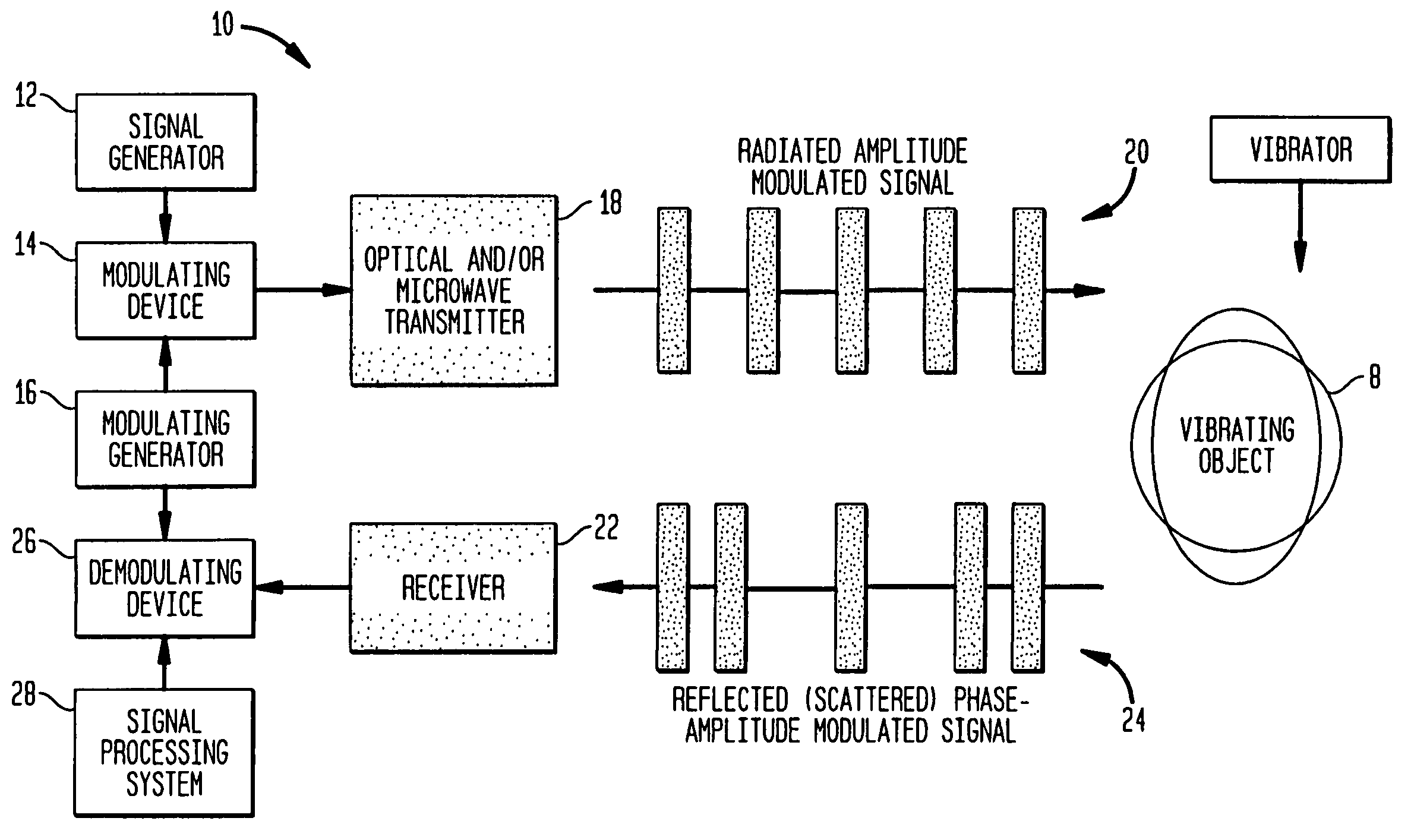
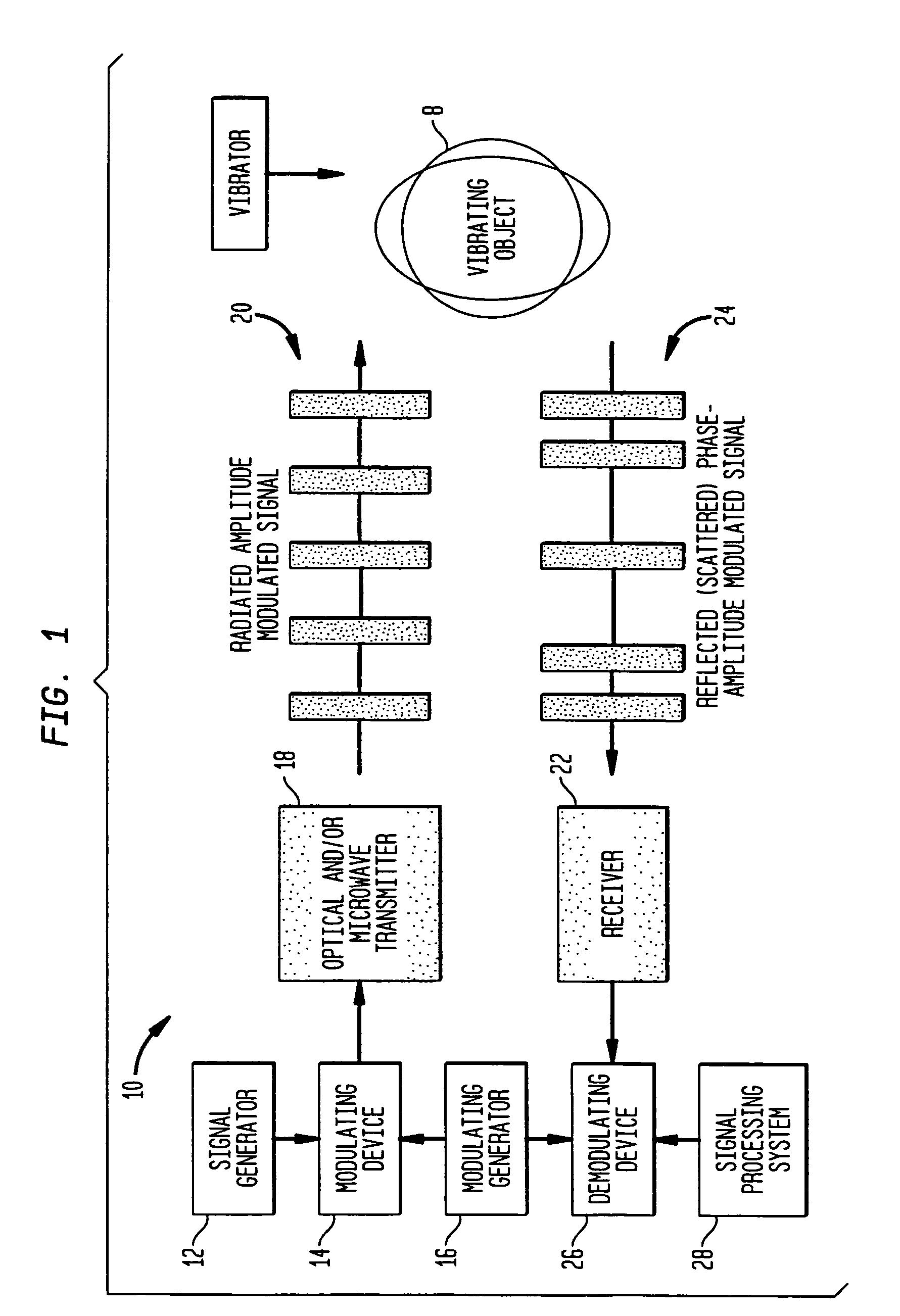
[0021]The present invention relates to a method and apparatus which employs phase or amplitude modulated electromagnetic probing waves (in optical or microwave frequency ranges) emitted toward a vibrating object. This is shown schematically in FIG. 1. The apparatus is generally indicated at 10. A signal is generated by the signal generator 12, and then modulated by the modulating device 14 which receives a modulating signal from the modulating generator 16. Preferably, the signal is amplitude modulated. The optical or microwave probing signals 20 are transmitted by transmitter 18 and remotely irradiate an object 8 of interest. The object 8 reflects and / or scatters the probing wave 20 toward to a receiver 22, where it is received. Vibration of object 8 causes additional phase modulation to the probing wave 20, based on the fact that object 8 is vibrating, which becomes amplitude / phase modulated signal 24. At the receiving end, the signal 24 is demodulated by demodulation device 26, a...


PUM


Abstract

A method and apparatus (10) is provided which employs phase or amplitude modulated electromagnetic probing waves (20) (in optical or microwave frequency ranges or both) emitted toward a vibrating object (8). The optical and/or microwave probing signals (20) remotely irradiate an object (8) of interest. The object (8) reflects and/or scatters the probing wave (20) toward a receiver (22). The reflected/scattered modulated signal (24) is received with a remote sensor (receiver) (22). Vibration causes additional phase modulation to the probing wave (20). At the receiving end, the signal is demodulated to extract and analyze the vibration waveform (26,28). The present invention can be utilized for nondestructive testing, monitoring of technological processes, structural integrity, noise and vibration control, mine detection, etc.

Description

[0001]This application claims the benefit of provisional application 60 / 150,224 filed Aug. 23, 1999.BACKGROUND OF THE INVENTION[0002]1. Field of the Invention[0003]The present invention generally relates to a method and apparatus for nondestructive testing, monitoring of technological processes, determining structural integrity, noise and vibration control, and mine detection. More specifically, the present invention relates to a phase-amplitude modulated electromagnetic wave (PAM-EW) vibrometer.[0004]2. Related Art[0005]Existing remote vibrometers are generally based on coherent laser generated signals. These devices, known as laser-doppler vibrometers, require precision and expensive optical elements (acousto-optic modulators, gas lasers, mirrors, beam splitters, etc.) A very precise, very coherent source is required, i.e. very stable phase characteristics. Fine adjustments are necessary to achieve a desirable effect. As a result, the laser-doppler vibrometers are quite expensive ...

Claims


Application Information

Patent Timeline
IPC IPC(8): G01N29/36
CPCG01N29/2412G01N29/30G01N2291/044G01N2291/015
Inventor DONSKOY, DIMITRISEDUNOV, NIKOLAYWHITTAKER, EDWARD A.
Owner STEVENS INSTITUTE OF TECHNOLOGY
Why Eureka
Try Eureka