Drive configuration for a skid steered vehicle

a technology of drive configuration and skid steer, which is applied in the direction of mechanical equipment, transportation and packaging, gearing, etc., can solve the problems of not revealing a practical embodiment of such a device, requiring oversized motors, and requiring large and heavy arrangements, etc., to simplify the packaging and design of the other components.

Inactive Publication Date: 2006-07-11
QINETIQ LTD
View PDF27 Cites 55 Cited by
  • Summary
  • Abstract
  • Description
  • Claims
  • Application Information

AI Technical Summary

Benefits of technology

[0031]A feature of this drive arrangement is the use of the controlled differential gear steer unit which causes the transmission of the regenerative steering powers directly through the motor shafts, removes the need for a separate steering cross-shaft and greatly simplifying the packaging and design of the other components.

Problems solved by technology

The system therefore, is not a mechanically regenerating system and has the same disadvantages as a two line system in that oversized motors are required.
A French Patent FR 2,382,362 describes the operation of a controlled differential but does not appear to disclose a practical embodiment of such a device.
Due to the use of bevel gears and the configuration for the two long meshing gears, such an arrangement would need to be large and heavy for a high power device.
The above described arrangements suffer from various disadvantages; including in some cases the need for over-rated motors to achieve steering, complex mechanical arrangements requiring multiple cross shafts and idler gears and / or complex motor configurations incorporating tubular shafts.

Method used


Image

  • Drive configuration for a skid steered vehicle
  • Drive configuration for a skid steered vehicle
  • Drive configuration for a skid steered vehicle

Examples


Embodiment Construction

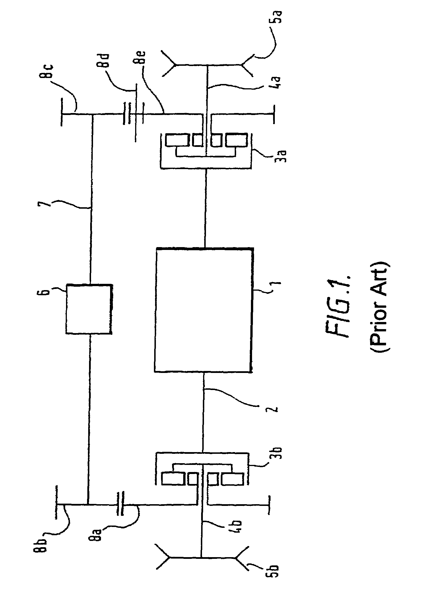
[0039]As can be seen from FIG. 1, the prior art drive configuration comprises a propulsion motor (1) mounted on a cross-shaft (2) which is coupled to the annuli of the two epicyclical steer differential (3a, 3b). The planet carriers of the two epicyclical steer differentials are connected to the output shafts (4a and 4b) and the track drive sprockets (5a and 5b). The steer motor (6) is mounted on a steer cross shaft (7). The steer cross shaft is coupled to the sun gears of the steer epicyclical differentials by a number of spur gears (8a, 8b, 8c, 8d, and 8e). An extra spur gear (8d) is used on one side to reverse the rotation of the sun gear. This layout is identical to that used in a conventional mechanical drive tank transmission, the propulsion motor is fitted in place of the gear range change pack and the hydraulic steer motor has been substituted for a electric motor. This is the basis of the electric drive shown in U.S. Pat. No. 4,998,591.

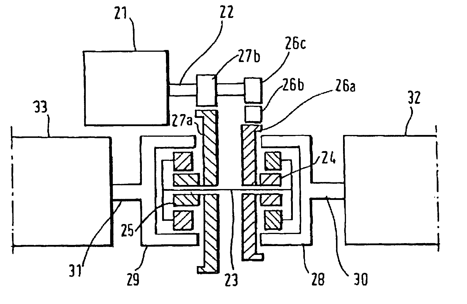
[0040]As can be seen from FIG. 2, a pr...


PUM


Abstract

An electric drive configuration for a skid steered vehicle comprises: a pair of propulsion motors (74a, 74b), each with a motor shaft protruding from both ends of the motor and mounted on the same axis across the vehicle, each being coupled at the outer end to drive one of a pair of tracks or set of wheels of the skid steered vehicle; a control differential steep gear unit (72) positioned between the two propulsion motors and in driveable communication with the inner ends of the two motor shafts: and a steer motor (71) in driveable communication with the controlled differential (72), the steer motor (71) being controllable from zero speed giving straight line running in which both motor shafts are coupled to run at the same speed, to a range of speeds in both directions of rotation giving steering capability in both directions.

Description

[0001]This application is the US national phase of international application PCT / GB02 / 01735, filed 17 Apr. 2002, which designated the US. PCT / GB02 / 01735 claims priority to GB Application No. 0109336.8, filed 17 Apr. 2001. The entire contents of these applications are incorporated herein by reference.BACKGROUND OF THE INVENTION[0002](1) Field of the Invention[0003]The present invention relates to a novel drive configuration for skid steered vehicles, including tracked or wheeled vehicles, for example but not limited to, a military armoured tank.[0004]A skid steered tracked vehicle is steered by forcing the two tracks to run at different speeds (skid steering). In the same way a wheeled skid steered vehicle is steered by forcing wheels to one side of the vehicle to run at different speeds to the wheels on the other side of the vehicle. For tracked vehicles, large driving force differences are required between the two tracks—large braking forces on the inner track and high driving forc...

Claims


Application Information

Patent Timeline
Patent Type & Authority Patents(United States)
IPC IPC(8): B62D11/06B62D11/00B62D11/02F16H37/02B60K7/00B62D11/14B62D11/16F16H48/00F16H48/06F16H48/10F16H48/30
CPCB60K7/0007B60K7/0015B62D11/16B62D11/14B60K17/046B60K2007/0092F16H2048/02F16H48/06F16H48/10F16H48/30
Inventor THOMPSON, ROBERT W
Owner QINETIQ LTD
Why Eureka
Try Eureka