High spectral purity microwave oscillator using air-dielectric cavity

a microwave oscillator and dielectric cavity technology, applied in oscillator generators, pulse automatic control, electrical equipment, etc., can solve the problems of relatively high-level spurious lines above and below, very high frequency of random noise, delay-line discriminators, etc., to mitigate cost and complexity penalties

Inactive Publication Date: 2006-07-11
GOVERNMENT OF THE UNITED STATES OF AMERICA AS REPRESENTED BY THE SEC OF COMMERCE THE NAT INST OF STANDARDS & TEHCNOLOGY
View PDF6 Cites 7 Cited by
  • Summary
  • Abstract
  • Description
  • Claims
  • Application Information

AI Technical Summary

Benefits of technology

[0023]The present invention is directed to an oscillator comprising a normal air / vacuum-filled power-cavity thereby mitigating cost and complexity penalties of the prior art while achieving the same or better performance.
[0032]b) a model of an oscillator noise that is accurate, indicating that unprecedented discriminator signal-to-noise ratio and consequently ultra-low wideband noise from a microwave oscillator is possible;
[0040]a) It is possible to attain coupling values very close to unity (critical coupling) with ease and with excellent reproducibility. This is in contrast to the difficulty of achieving unity coupling with solid dielectrics and / or in closed cryogenic systems. Unity coupling enables significant reduction of the noise contribution due to the circulator that must be used in conjunction with the discriminator.
[0041]b) It is possible to obtain high output power for the final stabilized oscillator directly from the transmission port of the cavity, which can be very loosely coupled in order not to degrade the cavity Q further. Due to the high power into the cavity, no additional amplification (a source of additive noise) is needed for the final output from the cavity to the user's application.
[0043]d) The present invention is lower in cost and easier to fabricate, analyze, and test when compared to the SLC and other prior systems that use, for example, low-temperature solid-dielectric resonators.

Problems solved by technology

That increased noise level is usually at a rate of at least 1 / f3 resulting in random noise that is very high close to the carrier frequency.
Unfortunately, delay-line discriminators have a response that repeats with spacing f=1 / (delay).
For long delays, nearby responses cause relatively high-level spurious lines above and below a given main discriminator response.

Method used


Image

  • High spectral purity microwave oscillator using air-dielectric cavity
  • High spectral purity microwave oscillator using air-dielectric cavity
  • High spectral purity microwave oscillator using air-dielectric cavity

Examples


first embodiment

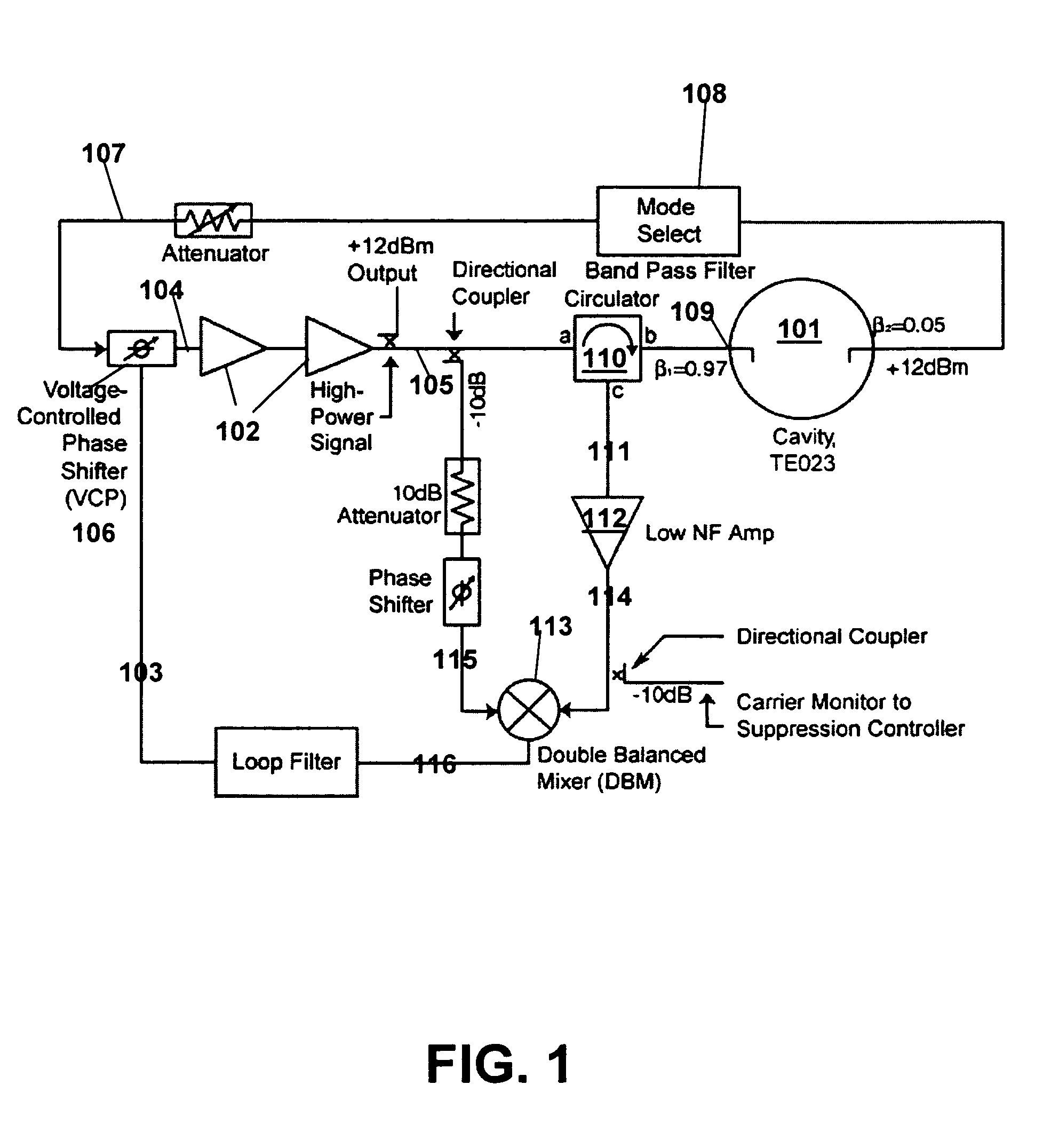
[0050]The present invention is based on proven oscillator designs that use the carrier-suppression technique, discussed below. FIG. 1 illustrates an apparatus, according to the present invention, that uses a high-Q cavity 101 to self-sustain an oscillating signal formed by feeding back a power-amplifier output signal 103 (second output signal) into its input 104. Residual phase noise in the amplifier stages 102 is suppressed with a voltage-controlled phase shifter (VCP) 106 at the amplifier's input 104. The VCP's 106 input signal is the phase error between the oscillating signal and the cavity resonance mode (third output signal). A bandpass filter 108 selects the mode.

second embodiment

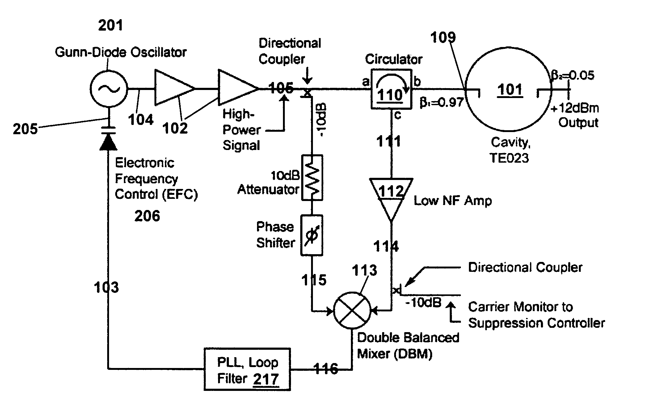
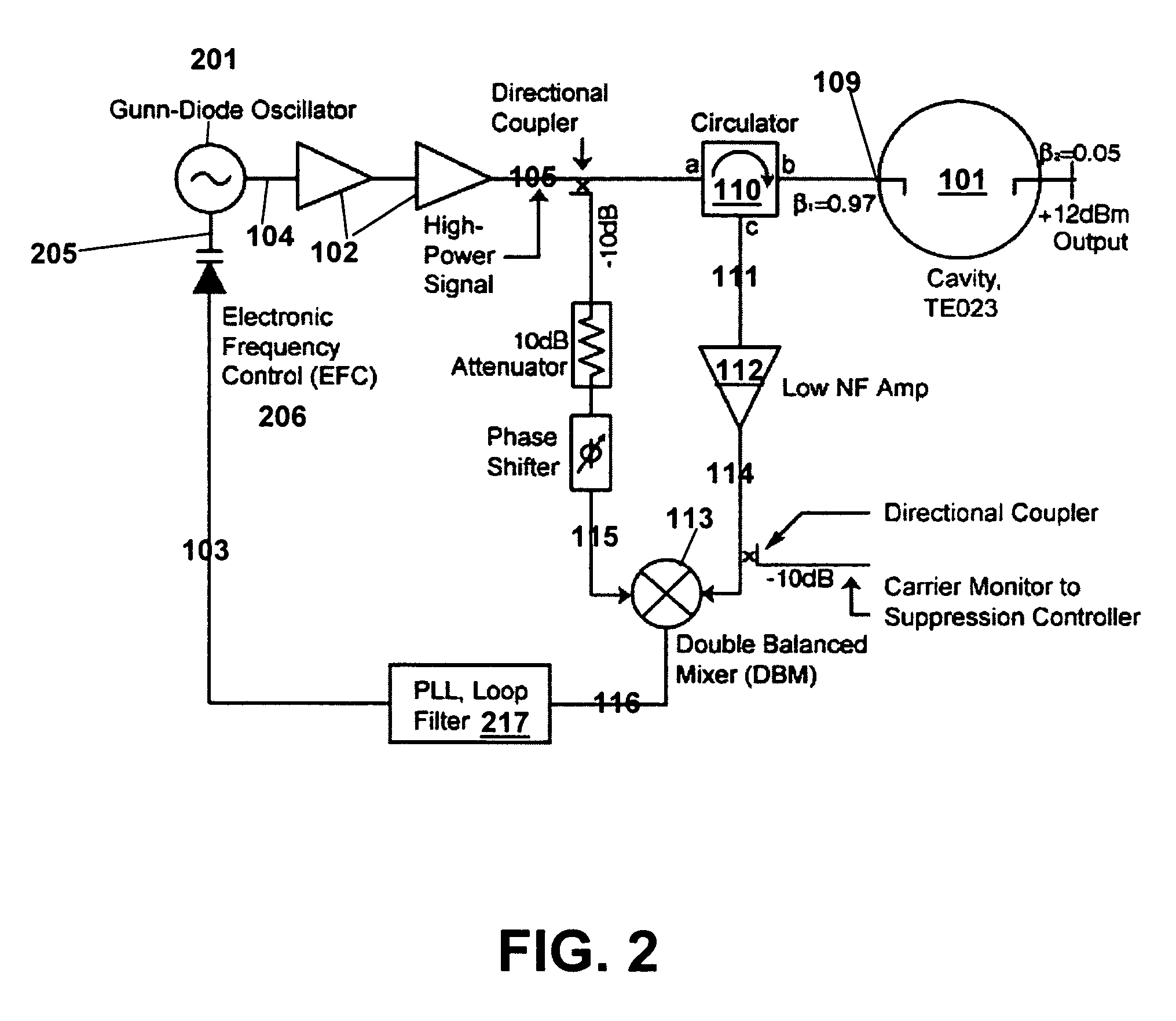
[0051]FIG. 2 illustrates an apparatus, according to the present invention, in which a separate voltage-controlled oscillator (VCO) 201 is locked to the center of a cavity resonance mode. The mode is selected by the VCO 201 frequency.

[0052]Both embodiments use the same frequency discriminator and phase noise detector, whose intrinsic noise sets the lower limit on the phase noise of the oscillating signal. Four factors are important to achieving significant improvement in the spectral purity of microwave oscillators in both embodiments:[0053]a) sensitivity of the detector with its high-Q frequency discriminator must be as high as possible to exploit the low inherent resonator noise;[0054]b) of all the possible types of resonators that can be used as a phase detector, conventional air-dielectric high-Q cavities are most ideally suited for handling large power levels with minimum complexity and cost;[0055]c) the flicker noise behavior in air-dielectric resonators is below present measur...


PUM


Abstract

A high spectral purity microwave oscillator is provided. The Oscillator uses an air-dielectric cavity and employs the known carrier-suppression technique. In one embodiment, the oscillator employs a high-Q cavity to self-sustain an oscillating signal formed by feeding back into its input a power-amplified output signal of the cavity in which residual phase noise in the amplifier stages is suppressed. A bandpass filter selects the cavity mode. FIG. 1 illustrates this embodiment. Another embodiment suppresses the noise of a voltage-controlled oscillator whose frequency and power-amplified output interrogates the cavity mode. FIG. 2 illustrates this embodiment.

Description

CROSS-REFERENCE TO RELATED APPLICATION[0001]The present application claims priority to provisional application Ser. No. 60 / 486,524 filed Jul. 11, 2003, the contents of which are incorporated herein by reference in their entirety.BACKGROUND OF THE INVENTION[0002]1. Field of the Invention[0003]The present invention relates to a low noise microwave oscillator. More particularly, the present invention relates to an oscillator using a high power radio frequency (RF) input into an air or evacuated conventional resonator to reduce noise.[0004]2. Description of the Related Art[0005]Microwave oscillators of high spectral purity are required as a local reference or clock signal in secure communications protocols, very high-speed jitter-sensitive modulation-demodulation schemes, and high-resolution digital signal processing applications such as imaging radar. These oscillators are designed to produce an oscillating signal at one frequency, the resonant or carrier frequency νres, and to use a t...

Claims


Application Information

Patent Timeline
Patent Type & Authority Patents(United States)
IPC IPC(8): H03B5/18H03B9/12H03L7/00H03L7/081H03L7/099
CPCH03B5/1817H03B9/12H03L7/099H03L7/081H03L7/00
Inventor HOWE, DAVID A.GUPTA, AMITAVA SENNELSON, CRAIGWALLS, FRED L.
Owner GOVERNMENT OF THE UNITED STATES OF AMERICA AS REPRESENTED BY THE SEC OF COMMERCE THE NAT INST OF STANDARDS & TEHCNOLOGY
Why Eureka
Try Eureka