Assembly for correcting laser illumination emitted from a laser light source and method for producing said assembly

a laser light source and laser light source technology, applied in lasers, laser optical devices, recording devices, etc., can solve the problems of difficult production of assembly, difficult production, and inability to meet the requirements of the application, and achieve the effect of easy production

Inactive Publication Date: 2006-07-11
LIMO GMBH
View PDF19 Cites 11 Cited by
  • Summary
  • Abstract
  • Description
  • Claims
  • Application Information

AI Technical Summary

Benefits of technology

[0005]There is provided, correction means that are made as a prism array. One such prism

Problems solved by technology

In this arrangement, which is known from the art, it has been found to be especially disadvantageous that the instrument used for bending the glass fibers has a relatively complex structure, because the glass fibers at some points must be deliberately bent by only a few microns or fractions of microns relative to other points.
The disadvantage here is that on the one hand for each of these plane-parallel plates a

Method used


Image

  • Assembly for correcting laser illumination emitted from a laser light source and method for producing said assembly
  • Assembly for correcting laser illumination emitted from a laser light source and method for producing said assembly
  • Assembly for correcting laser illumination emitted from a laser light source and method for producing said assembly

Examples


Embodiment Construction

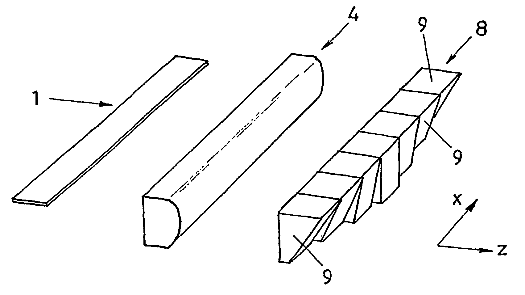
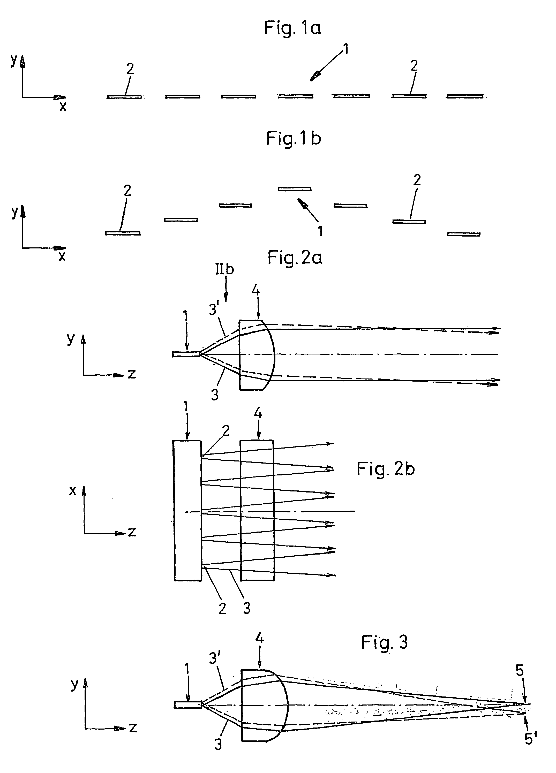
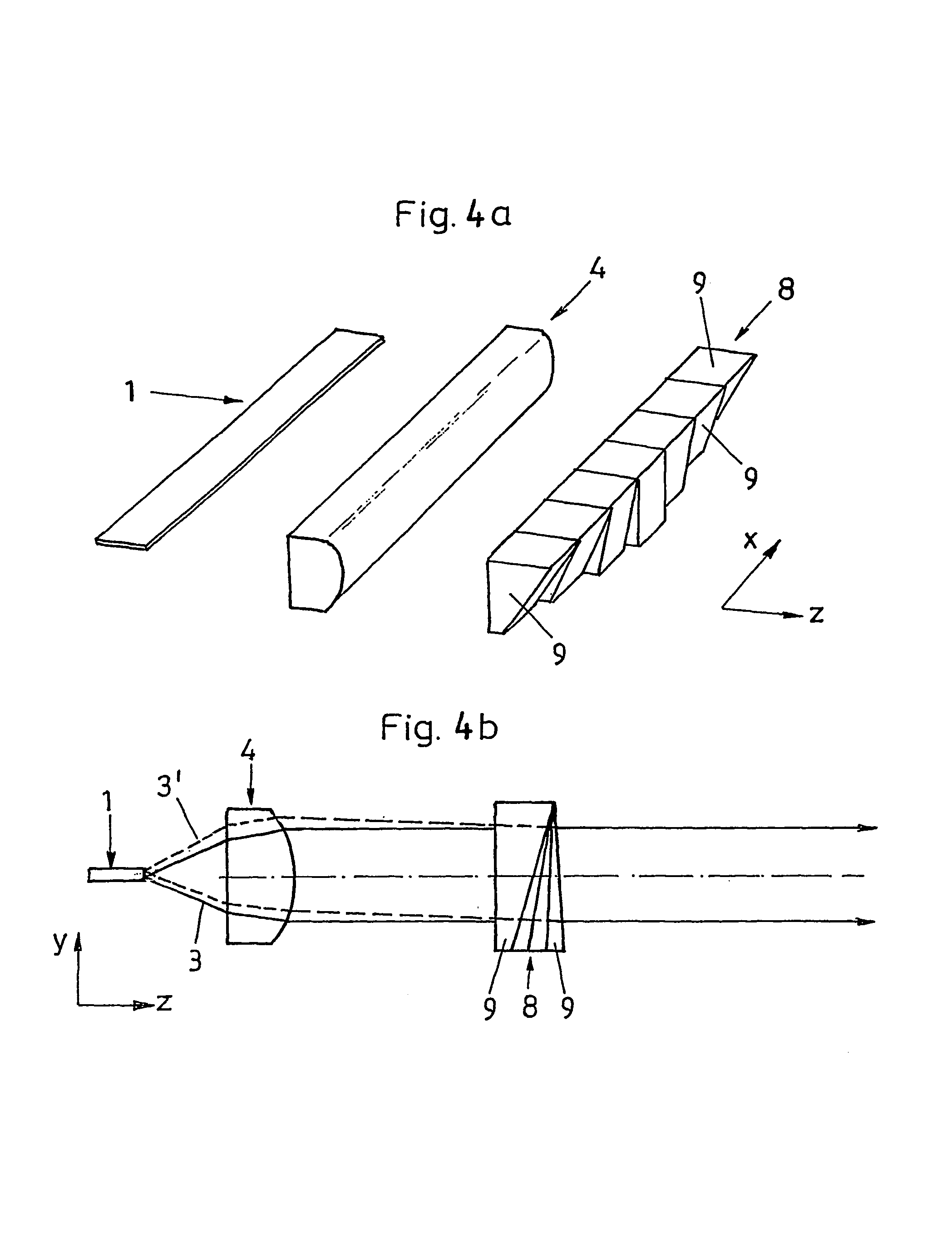
[0027]FIGS. 1 to 4 and FIGS. 6 and 7 show coordinate systems for illustrating the orientation.

[0028]FIG. 1a shows a schematic view of a laser light source 1 with emission sources 2 located in a row. These laser light sources 1 are generally made as laser diode bars. The dimensions can be, for example, such that the entire width of the laser diode bar in the direction of the illustrated row is roughly 10 mm, conversely the width in the direction of the row of the individual emission sources 2 is roughly 200 microns. The proportions are not true to nature here, but are shown only schematically in order to illustrate the problems associated with the “smile” distortion which is detailed below. The spread of the emission sources 2 in one direction perpendicular to the direction of the row is for example 1 micron.

[0029]FIG. 1b shows emission sources 2 which are not ideally arranged and thus which roughly reproduce the light emitted from the laser diode bar. It is clear that the individual...


PUM


Abstract

The invention relates to an assembly for correcting laser illumination emitted from a laser light source, comprising a laser light source, which has linear emission sources that are arranged in a row in a first direction (X), whereby in addition, the emission sources that are arranged essentially in a row are at least partially offset relative to the row in a perpendicular direction (Y) in relation to the first direction (X). The assembly also comprises corrective elements, which can correct the laser illumination emitted from the laser light source in such a way that the spatial distortion of the laser illumination, caused by the offset position of the emission sources relative to the row, is compensated. According to the invention, the corrective elements are configured as a plate array that comprises a number of plate elements consisting of substantially plane-parallel plates that are transparent to the laser illumination used. At least two of the plate elements have a different thickness and the corrective mans is located in the laser illumination emitted from the laser light source, in such a way that the light beams emitted from at least two emission sources that are offset in relation to one another are subjected to a respective beam offset of a different magnitude by two different plate elements, thus compensating the distortion caused by the offset position of the emission sources. The invention also relates to a method for producing the aforementioned assembly.

Description

BACKGROUND OF THE INVENTION[0001]This invention relates to an arrangement for correction of laser radiation emanating from a laser light source, including a laser light source which has linear emission sources which are located essentially in at least one row in a first direction, furthermore the emission sources located essentially in a row being offset in the direction perpendicular to the first direction at least partially to the row, and the arrangement furthermore having correction means which can correct the laser radiation emanating from the laser light source such that the three-dimensional distortion of the laser radiation caused by the offsetting of the emission sources to the row is equalized. Furthermore this invention relates to a process for producing this arrangement.[0002]An arrangement and a process of the initially mentioned type is known from U.S. Pat. No. 6,166,759. In the arrangement described, the so-called “smile” distortion, which generally occurs in laser di...

Claims


Application Information

Patent Timeline
IPC IPC(8): G02B5/04G02B27/00G02B27/09H01S3/00H01S5/00H01S5/40
CPCG02B27/09G02B27/0972G02B19/0014H01S5/4025G02B19/0057H01S5/005
Inventor MIKHAILOV, ALEXEILISSOTSCHENKO, VITALIJ
Owner LIMO GMBH
Why Eureka
Try Eureka