[0019]The object of the present invention is to enhance how
error correction coding technology can work together with recording / readback
signal processing signals that make active use of PRML signal-
processing techniques, particularly maximum-likelihood sequence decoding techniques.
[0020]In conventional technologies, data decoding using maximum-likelihood sequence decoding and error correction using
error correction coding have been implemented as independent operations. In error correction performed after data decoding, if all decoding errors cannot be corrected the same information is re-read from the recording medium (retry operation) and predetermined
signal processing and data decoding operations are performed again. To perform this re-reading of data, many recording / readback devices such as magnetic disk devices must move a readback
transducer (head) to a predetermined position where the recorded information is placed, thus significantly increasing the processing time required for data readback. This means that
data access performance of the recording / readback device decreases. Thus, providing reliability through this method has its own limits. To restore reliability in the decoding of data and to maintain device reliability for high-density recordings, it is necessary to both improve decoding reliability in maximum-likelihood sequence decoding operations as well as increase effectiveness in error correction.
[0023]Due to the principles behind the decoding performed in maximum-likelihood decoding, burst decoding errors, in which errors are propagated to a plurality of code positions, are often generated. However, if the partial error correction information described is used so that correct code information can be provided for erroneous codes in these burst decoding errors, then all the erroneous codes in the
burst error can be corrected and eliminated in a cascading manner. By eliminating
burst error propagation in maximum-likelihood sequence decoding, the correction load resulting from long errors can be eliminated from subsequent error correction operations and this significantly improves the effectiveness of the correction operations. As a result, the repeated data decoding and error correction operations serve to mutually reinforce their effectiveness. Thus, by repeatedly performing decoding operations on the same readback signal stored in the recording / readback
system, the reliability of the decoded data can be improved without requiring the recorded information to be re-read from the medium.
[0029]In a typical example of the present invention, maximum-likelihood sequence decoding is performed to determine a single decoded
data series that appears most reliable out of a plurality of candidate decoded
data series (data transitions) (first step). Next,
error checking a correction is performed on this decoded
data series (second step). If an error that cannot corrected is found, the position / content of the error is fed back to the maximum-likelihood sequence decoding operation. In the maximum-likelihood sequence decoding operation, the decoded data series containing the error is eliminated from the candidate decoded data series and a decoding operation is performed again. Also, decoding is performed again using candidate decoded data series consisting only of decoded data series that do not contain errors (correct decoded data series) (third step). If errors can be corrected by the error correction provided by the second step, the corrected data can serve as the correct data.
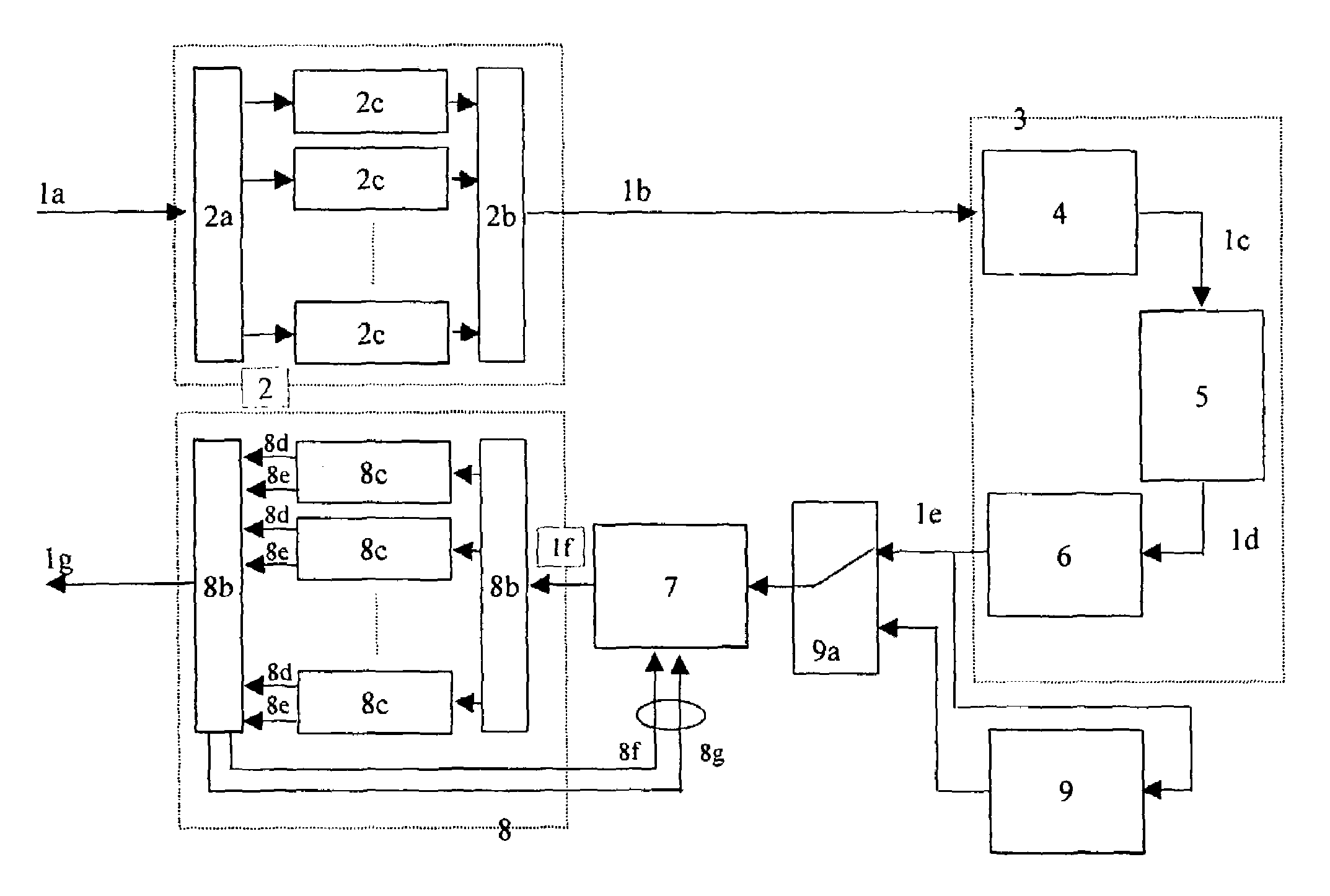
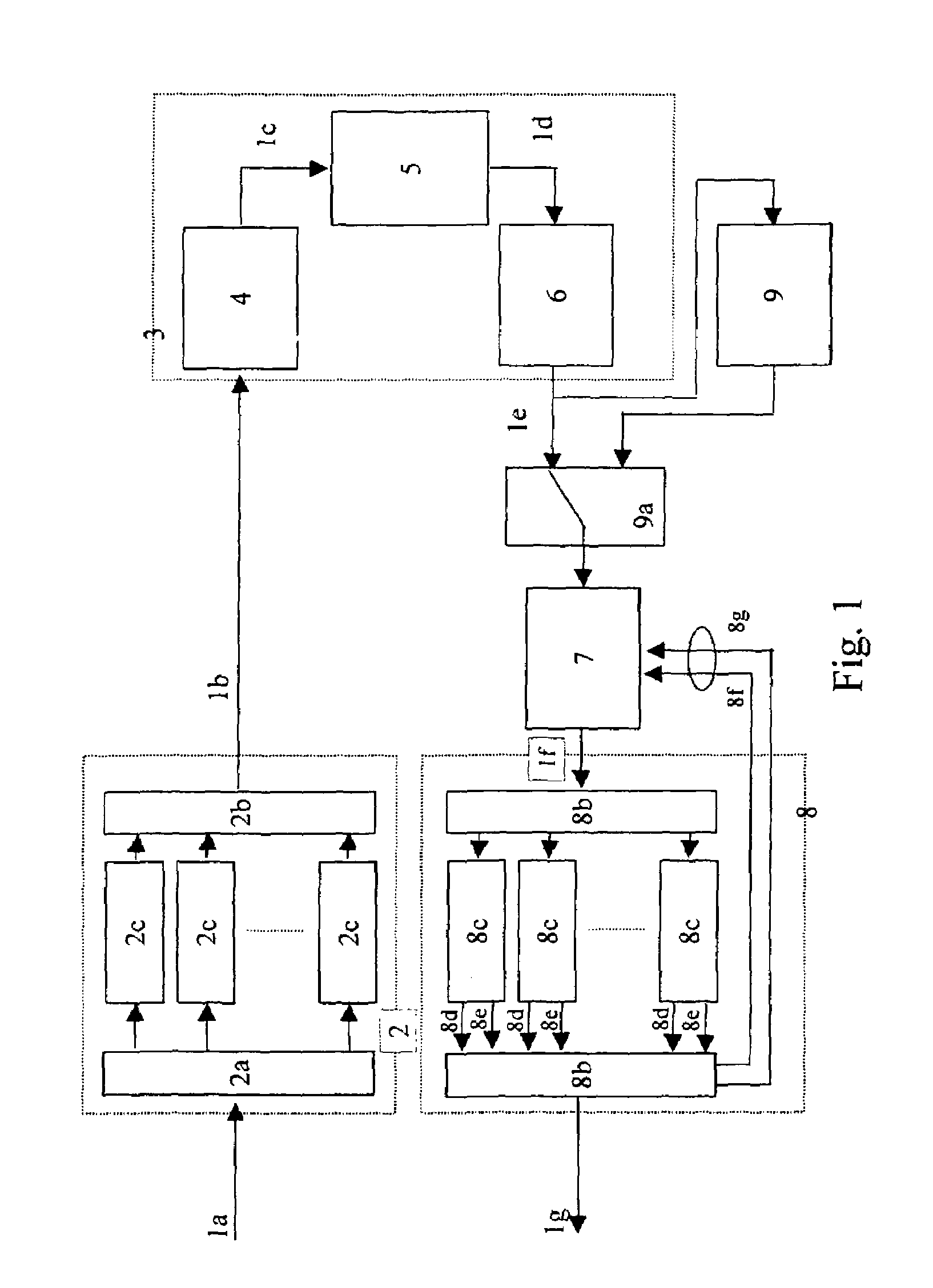
[0030]The basic architecture of a
signal processing device implementing the readback method described above includes: a decoding circuit decoding an information data series and generating a decoded data series; a data detecting circuit detecting decoding error data from the decoded data series and outputting error information regarding the decoding error data; and a feedback signal path sending the error information from the error data detecting circuit to the decoding circuit as input. The decoding circuit uses the error information to perform a re-process the same position in the information data series that has already been processed. It would be desirable to have this type of signal processing device provided in the form of a single-
chip semiconductor integrated circuit (LSI). By using this type of LSI in a circuit for a magnetic or optical information recording device, an information recording device that can accurately decode signals recorded on an information recording medium can be provided. The LSI can also contain a recording circuit for recording signals to the recording medium, a
control circuit for providing overall control over the information recording device, or the like, thus providing a single-
chip disk controller. This type of architecture allows compact implementation of recording / readback devices as well as providing higher recording densities in recording / readback devices.

